Use the VBOX Setup software to configure the Wireless Wheel Speed Sensor input on a VBOX data logger.
You can connect and configure the sensors in two ways:
- Racelogic Module – VBOX data loggers will detect the receiver as a Racelogic Module, and automatically load the correct CAN input configuration.
- CAN Input – VBOX data loggers log the receiver data as CAN signals. You must load the relevant DBC file and configure the CAN input manually.
Product Limitation
Only VBOX 4 data loggers support and recognise the Wireless Wheel Speed Sensors as a Racelogic Module.
- Connect the power supply to the PWR port on VBOX 4.
- Connect VBOX 4 to a Laptop/PC with VBOX Setup installed.
- USB connection: Use RLCAB042 to connect from the USB-B port on VBOX 4 to a USB-A port on the PC.
- Bluetooth connection: Connect to VBOX 4 via Bluetooth.
- Connect the Wheel Speed Sensor Link Data Receiver to VBOX 4 (see the Installation page).
- Activate the Wheel Speed Sensors with the supplied Magnetic Switch (WSMAGSW).
- Start VBOX Setup.
- If you use a USB connection, select the relevant COM port and click Connect,
- Open the Channel Setup menu.
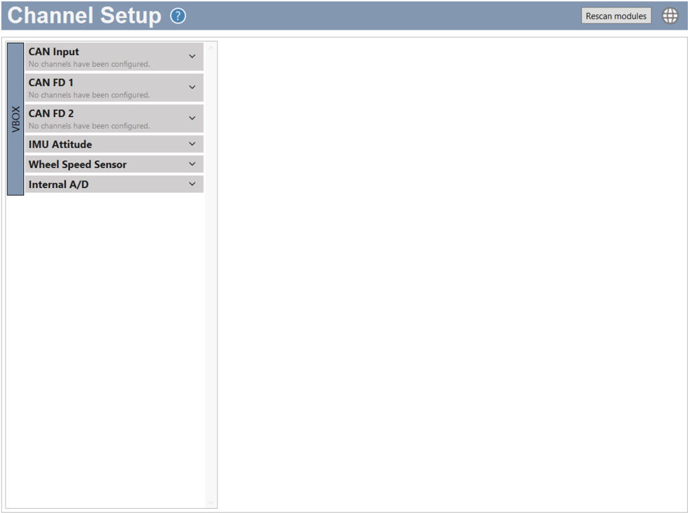
- In the input list, select the Wheel Speed Sensor Input.
- Select the Wheel Speed Sensor Channels you want to log by ticking/unticking the respective boxes in the Log column.
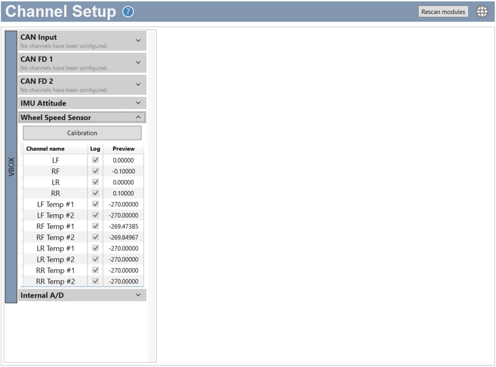
The Wheel Speed Sensors output rotational speed. VBOX Setup can auto-calibrate the sensors to convert RPM to vehicle speed.
The auto-calibration calculates a scale factor for each sensor.
Before you calibrate, make sure that all the Wheel Speed Sensor equipment is installed and connected as described in this guide and that the VBOX 4 Data Logger is connected and configured as required.
- Click Calibrate to start
- Accelerate to the target speed.
- Drive in a straight line.
- Hold the target speed and heading steady for 5 seconds.
VBOX Setup starts a 5-second countdown when it detects the correct speed and heading. Heading is the direction of travel reported by the GPS.
If the speed goes above or below the target speed, or heading changes, VBOX Setup will reset the calibration and wait for the correct speed and heading again before restarting the calibration.
When the countdown finishes, VBOX Setup applies the scale factors and completes the calibration.
The Wheel Speed Sensors are now ready for testing.
- Download the RLWSSENSOR 1.dbc file.
- Connect the power supply to the PWR port on VBOX 4.
- Connect VBOX 4 to a Laptop/PC with VBOX Setup installed.
- USB connection: Use RLCAB042 to connect from the USB-B port on VBOX 4 to a USB-A port on the PC.
- Bluetooth connection: Connect to VBOX 4 via Bluetooth.
- Connect the Wheel Speed Sensor Link Data Receiver to VBOX 4 (see the Installation page).
- Activate the Wheel Speed Sensors with the supplied Magnetic Switch (WSMAGSW).
- Start VBOX Setup.
- If you use a USB connection, select the relevant COM port and click Connect,
- Open the Channel Setup menu.
- Select CAN Input from the list of available CAN Signal options on the left.
This will open an Add CAN Signals pane on the right side of the window.
- Select Import Import from dbc/ref as the source.
- Click Browse and navigate to the location with the relevant .dbc file.
- Click Open.
The channels in the file will be listed under Select Channels to Log.
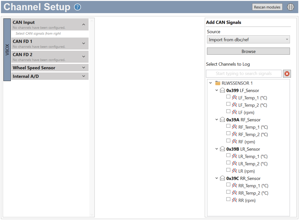
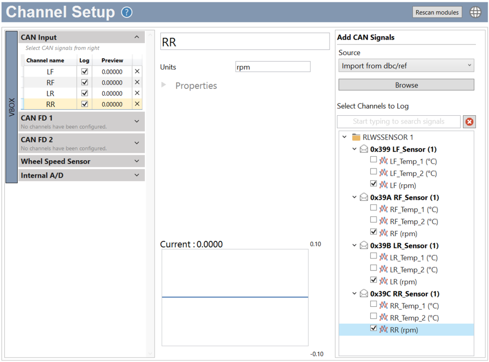
- Select the channels you want to log from the list.
- The selected channels will be displayed in the CAN Input section, with live previews when connected and ready.
The Wheel Speed Sensors output rotational speed. You can calculate the required scale factor and add it to the channels in the VBOX Setup CAN Input to convert RPM to vehicle speed.
Vehicle Speed = Sensor Speed × Scale Factor
- Stabilise the vehicle at a known speed.
- Drive the vehicle at a steady, known reference speed (e.g., 40 km/h, 60 km/h, or 50 mph)
- Maintain this speed for approximately 4 seconds
Use GPS speed from the VBOX data logger or a validated reference as the true vehicle speed.
- Average the reference vehicle speed.
- Compute the average vehicle speed over the 4-second interval
- This becomes your true speed value
Example: Vehicle speed (avg) = 60.0 km/h
- Average the sensor output.
- Compute the average RPM (or raw sensor value) over the same 4-second window
Example: Sensor speed (avg) = 820 RPM
- Calculate the scale factor.
Scale Factor = Average Sensor Speed / Average Vehicle Speed Example: Scale Factor = 60.0 / 820 = 0.07317
- Enter the scale in for the Wheel Speed Sensor channels in VBOX Setup.
- Open VBOX Setup -> Channel Setup -> CAN Input -> Wheel Speed Sensor.
- Select the relevant Wheel Speed Sensor channel from the list of available channels by clicking on the channel name.
- Edit the channel scale by expanding the channel properties and entering the following into the applicable settings:
Scale = calculated value
Offset = 0 (unless the sensor requires bias correction)
- Repeat for all required wheel speed sensor channels.
Use either: The same scale (if tires and sensors are identical), or individual scales (if there are small tolerances).
- Click Write to unit to load the new settings into VBOX 4.
- The live previews for the channels should now all match, and increase and decrease in line with, the vehicle speed.
IMPORTANT
- If you are using a VBOX 3i, you can find configuration information here.
- If you are using a third-party data logger, you must load this RLWSSENSOR 1.dbc file into your data logger, configure the CAN input and then scale the signal, as described above.
Refer to the user guide for your VBOX data logger for more information about how to configure CAN inputs.