Best practice is to make sure that you have all the necessary equipment ready before you start installing systems on vehicles.
Required Equipment to set up your VBOX 4 unit:
- VBOX unit
- Power cable
- USB cable
- Antenna(s)
- Antenna cable(s)
- Laptop
- VBOX Setup
Modules and accessories
This is a list of peripherals that you can use with your VBOX 4 unit. Click on the product name to see the kit you need to use it.
- MFD Touch Unit (RLVBMFDT)
- Cable (RLCAB005-C)
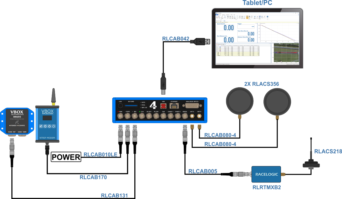
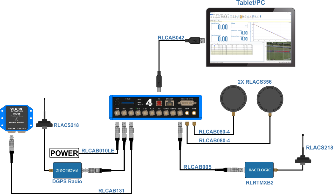
- IMU unit
- IMU cable (RLCAB131)
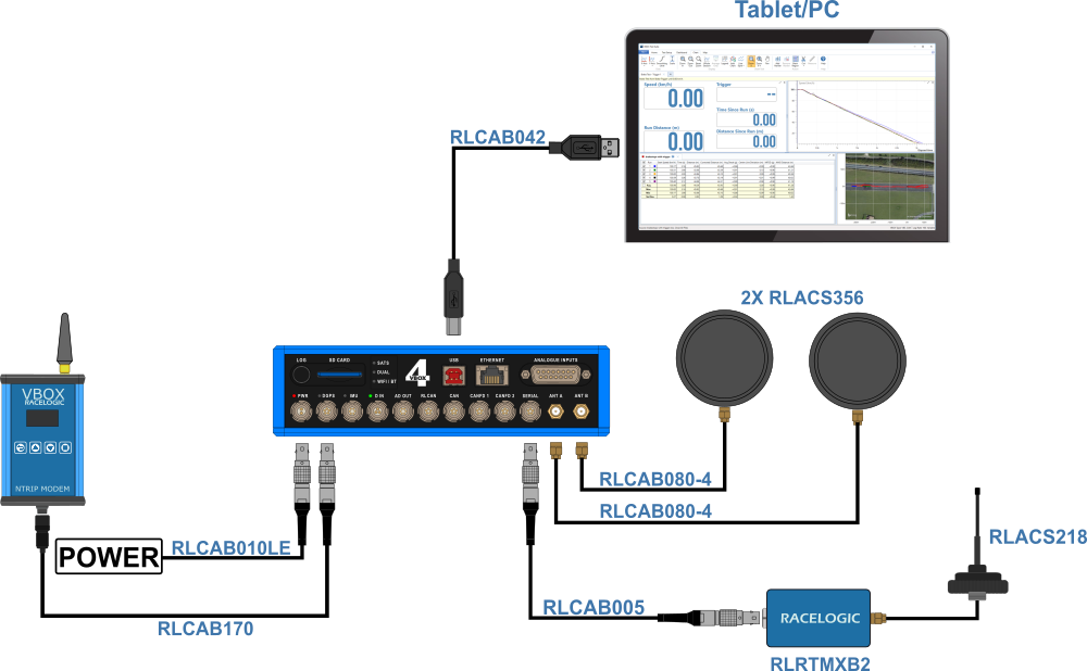
- NTRIP Modem
- Supplied NTRIP antenna
- SIM card/Mobile Phone
- NTRIP to VBOX Cable (RLCAB170)
- Laptop/mobile device for configuration
- Network information (if using SIM Card and internal modem)
- Base Station Unit
- Pole/Mast
- Antenna (ACS279)
- Antenna Cable (RLCAB101-3)
- Base Station Radio (RTM24MBS)
- Radio Antenna (RLACS218)
- Cable (RLCAB105)
- Radio Unit (RTM24MBC)
- Radio Antenna (RLACS218)
- Cable (RLCAB005)
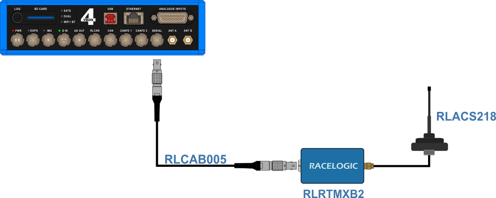
- Radio Unit (RTMXB2)
- Radio Antenna (RLACS218)
- Cable (RLCAB005)
- Survey Pole
- Survey Antenna (RLACS320)
- Survey antenna cable (RLCAB067)
- Survey Trolley kit
- TNC-to-SMA cable
- Surveying rucksack
- Telescopic pole
- Li-ion battery pack
- Stainless Steel Offset Bracket
- 5/8" stainless steel nut
- Rover wheel
- Telescopic handle
- Extension cable (SMA)
- Telemetry antenna
- Telemetry antenna bracket with nut
- Ground plane antenna
- TNC-to-SMA antenna cable
Model Limitations
This page references using two antennas. These are only available on VBOX 4 ADAS and VBOX 4 Dynamics models.
IMPORTANT
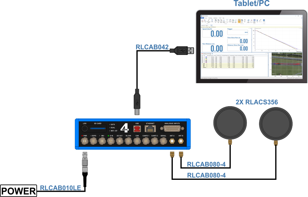
Connect the Antenna(s) to the VBOX unit before you connect the power.
- Connect one end of an antenna cable to the connector on the antenna(s).
- Place the antenna(s) on the roof of the vehicle.
You can read more about how and where to place the GNSS antennas here. - Connect the primary (A) and secondary (B) antennas to the A and B antenna ports on the VBOX 4 unit.
- Connect the power cable to the PWR port on the VBOX 4 unit.
- Connect the Tablet/Laptop to the USB port on the VBOX 4 unit with the USB cable (RLCAB042).
- Secure the VBOX unit in the vehicle.
You can, for example, place it in the foam insert in the carry case and secure the carry case in the back seat of the vehicle with the seat belt.
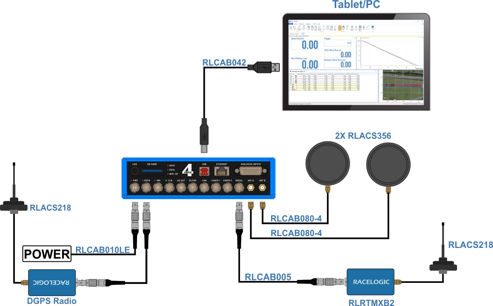
Differential GPS (DGPS), or Differential GNSS (DGNSS) as it is also known, is a system that provides positional corrections to GNSS signals. DGNSS uses a fixed, known position to adjust real-time GNSS signals to eliminate pseudorange errors. You can set up your own base station, use an already set up base station, or use an NTRIP modem to provide these correctional messages to your VBOX unit.
If you need information about how to set up your Base Station, you can find it here .
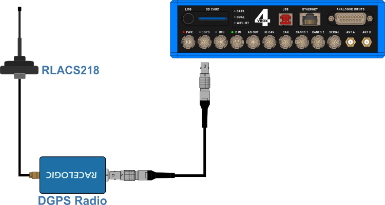
- Connect the Radio Antenna to the DGPS Client Radio.
- Place the Radio Antenna on the vehicle roof.
Note: The Radio antenna must be at least 50 cm away from any other radio antenna.
- Connect one end of an RLCAB005 cable to the port on the Radio unit.
- Connect the other end of the cable to the DGPS port on VBOX 4 unit.
If you need to configure your NTRIP Modem, you can find the instructions here .
Using SIM Card
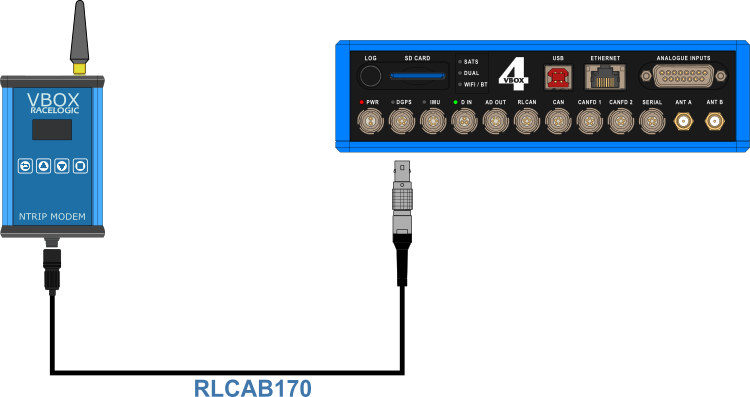
- Attach the supplied antenna (ANTMSTUBSMAM) to the SMA connector on the top of the NTRIP modem.
- Connect the Hirose end of the RLCAB170 to the Hirose connector at the bottom of the NTRIP modem.
- Connect the other end of the RLCAB170 cable to the DGPS port on the VBOX 4 unit.
This cable provides power to the modem from the VBOX unit. - When it has connected to the network provider, the unit will briefly display a Connected (mobile data supplier) message.
The NTRIP modem will reboot and attempt to connect to the internal modem you have configured. - When it has connected to the NTRIP server, the unit will briefly display the RTCM Streaming message.
- Check that the DGPS LED on the VBOX unit is solid green, indicating that it is receiving DGPS corrections.
Using Wi-Fi Connection
- Attach the supplied antenna (ANTMSTUBSMAM) to the SMA connector on the top of the NTRIP modem.
- Connect the Hirose end of the RLCAB170 to the Hirose connector at the bottom of the NTRIP modem.
- Connect the other end of the RLCAB170 cable to the DGPS port on the VBOX 4 unit.
This cable provides power to the modem from the VBOX unit. - The modem will power up and connect. When it is connected, the unit will briefly display “Wi-Fi Connected”.
If it cannot connect to the configured Wi-Fi hotspot on power up, it will automatically restart and become a configuration access point. See the instructions for configuring the NTRIP modem for the first time for the steps to configure the Wi-Fi hotspot again. - When it has connected to the NTRIP server, the unit will briefly display the RTCM Streaming message.
- Check that the DGPS LED on the VBOX unit is solid green, indicating that it is receiving DGPS corrections.
Racelogic's Inertial Measurement Units provide highly accurate measurements of pitch, roll, and yaw rate using three rate gyros, as well as X, Y, and Z acceleration from three accelerometers.
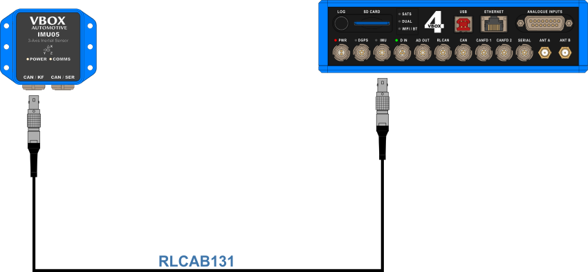
- Mount the IMU in the test vehicle (use the appropriate method based on your IMU variant, mounting accessories and test scenario).
- Connect one end of the RLCAB131 cable to the CAN/KF port on the IMU unit.
- Connect the other end of the RLCAB131 to the IMU port on the front panel of the VBOX 4 unit.
- Apply power to the VBOX unit.
IMPORTANT
If you are using IMU Integration, you must disable it before you set any vehicle or line reference points. You can enable it again after you have finished setting the points.
Integration
When you have connected the IMU to the VBOX unit, you must configure the IMU integration in VBOX Setup.
Initialisation
When using IMU integration, an initialisation phase is required. This will happen when the IMU is connected to the VBOX unit after being set up. The initialisation process will automatically run after the VBOX unit has successfully gained satellite lock. When the initialisation process is complete, the IMU LED on the front panel of the VBOX unit will start flashing green.
Kalman Filter Initialisation
When using an IMU filter it is important to perform the full calibration procedure before meaningful testing commences. The calibration procedure is a series of specific manoeuvres that should be performed that help the Kalman filter characterise the outputs from the IMU.
Kalman Filter Calibration
If you have enabled IMU Integration, you must perform the full calibration procedure before you can start to produce meaningful test results. The calibration procedure is a series of specific manoeuvres that you should perform to help the Kalman Filter characterise the outputs from the IMU.
If you do not perform the calibration procedure, the Kalman Filter will still function. It may, however, not produce a high level of accuracy until after you have performed dynamic manoeuvres in the X and Y plane (i.e. left and right-hand turns, braking and accelerating) which could take several minutes of driving.
Recommended Procedure
- Park the vehicle in an open area where the GNSS antenna has a clear view of the sky.
- Make sure that you have RTK fix.
- Remain static and wait for the IMU to complete the 30-second stationary initialization.
Note: If the IMU detects movement before the initialisation finishes, the 30-second process will restart when the vehicle is stationary again.
- When the LED on the front panel of the IMU changes from flashing orange to flashing green, drive forward to complete the initialisation of the IMU.
- Continue to an open area to perform the calibration procedure.
- Drive in a figure of eight at least twice. The vehicle should be at a speed of more than 5 km/h during this procedure to generate sufficient force for the calibration process.
Note: If you cannot do figure of eights, you can perform left/right slalom-type manoeuvres to achieve a similar effect.

- Accelerate hard from a standstill to 50 km/h or above. Perform a brake stop with a deceleration force of at least 0.5 g. You must perform this step twice.

Re-running the calibration
The Kalman Filter is constantly adapting its calibration depending on the information it receives from the GNSS receiver and the IMU. Therefore, if the vehicle is left stationary for a long time, or if an External IMU is moved from its mounting position, you should repeat the calibration procedure.
The calibration should also be repeated if there has been a communication break between the VBOX unit and the External IMU, such as:
- You power cycle either the VBOX unit or the External IMU.
- You change the VBOX IMU settings.
- You use the VBOX Setup Software to read the VBOX unit's settings.
- You use the VBOX Setup Software to read the External IMU settings.
- You perform a GNSS Coldstart.
What happens if you do not carry out this procedure?
If you cannot carry out this procedure as above, the speed accuracy will be reduced for the first few minutes, until the Kalman Filter is able to calibrate itself.
- Connect the Radio antenna to the Radio unit.
- Place the antenna on the car roof.
Note: The Radio antenna must be at least 50 cm away from any other radio antenna.
- Connect one end of an RLCAB005 cable to the port on the Radio unit.
- Connect the other end of the cable to the SER port on the VBOX 4 unit.
- Connect the RLCAB005-C cable to the bottom port on the right-hand side of the MFD Touch.
- Connect the other end of the cable to the RL CAN port on the VBOX 4 unit.

- Assemble the pole by screwing the two pole halves together.
- Attach the survey antenna (RLACS320) to the threaded top of the pole.
- Connect the antenna cable (RLCAB067) to the port on the survey antenna.
- Connect the other end of the antenna cable to the primary antenna port (A) on the VBOX 4 unit.
- Connect one end of a 5-pin Lemo cable (RLCAB005) to the Lemo port on the VBOX Telemetry Radio.
- Connect the other end of the cable to the SER port on the VBOX 4 unit.
- Connect the Li-ion battery pack to the PWR port on the VBOX 4 unit.
- Connect the TNC connector on the TNC-to-SMA cable to the connector on the GPS ground plane antenna.
- Connect the SMA connector to the primary antenna connector (A) on the VBOX 4 unit.
- Make sure that you secure all connected units in the surveying rucksack and that you tie the antenna cables to the telescopic pole with the supplied Velcro wraps.