When you first open the ADAS menu, you will see the Mode dropdown menu where you can set the mode for your connected VBOX unit, to Subject or Target.

Notes:
- If you have already calibrated the IMU Kalman Filter, enabling or disabling the ADAS mode will reset the Kalman filter and you will have to repeat the initialisation and calibration.
- Navigating away from the ADAS menu with unsaved changes will trigger the "write to unit" process.

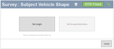
If you have set your ADAS mode to Subject, you can click the Edit button to configure your subject vehicle.
First, you must set the origin and forward direction. Move the survey antenna to the location of the primary antenna (antenna A) and click on the Set origin button.
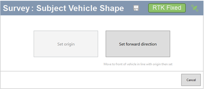
Then you move the survey antenna to the front of the vehicle in a straight line from the primary antenna (antenna A) and click on the Set forward direction button.


Next, you get to decide how you want to configure the vehicle points that form the subject vehicle shape.

When you have clicked on the Load from file button, you must navigate to the file you wish to use and click on the Load button.
When the file has been loaded, you will see a preview of the configured vehicle points and line reference points.
- You can use the zoom bar under the preview window to zoom in on points that are close together.
- You can also pan in the preview window to move between points after zooming in.
- You can modify the configured points manually if necessary.
Use the Clear button if you want to remove all set points.

Vehicle Points
You can configure up to 24 vehicle points where you need them.
Reference Points
You can also add up to 3 line reference points in this window. You need to configure at least one line reference point if you configure a line.
The preview window will show you your points as you add them.
- Vehicle points are blue and numbered.
- Line reference points are yellow and lettered.
This is a great way to quickly confirm that your vehicle shape is looking as expected and that your line reference points are where you want them.
- You can use the zoom bar under the preview window to zoom in on points that are close together. You can also pan in the preview window to move between points after zooming in.
- You can edit added points by changing the values in the X and Y boxes for each point.
- You can delete a point by clicking on the bin icon to the right of the point.
Click OK when you have finished surveying your points.

The software will check the vehicle points to see if they are in order. If the points are not in order, the software will display a new window, giving you the choice to continue using the original points or to use a set of reordered points.
If you choose to edit points, the survey window will open with the already set points.
- You can edit any set point by changing the values in the X and Y boxes for each set point.
- You can delete a point by clicking on the bin icon to the right of the point.
If you choose to edit points, the survey window will open with the already set points.
- You can edit any set point by changing the values in the X and Y boxes for each set point.
- You can delete a point by clicking on the bin icon to the right of the point.
IMPORTANT
You must add at least one ADAS object when configuring in Subject Mode. If you do not add an ADAS object, the ADAS mode will be set to Disabled when you click Write to unit.
An overview of the configured targets with the option to delete or edit specific targets.

Click Add Remote VBOX Target to open the Target vehicle shape window and configure the remote targets needed. You can set a maximum of 3 remote targets.
Note: You can have max 5 targets in total including remote and static targets.
- Set the origin and forward direction.


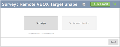
- Move the survey antenna to the location of the primary antenna (antenna A) and click on the Set origin button.
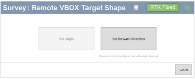
- Move the survey antenna to the front of the vehicle in a straight line from the primary antenna (antenna A) and click on the Set forward direction button.
- Decide how you want to configure the target vehicle shape.

Vehicle Points
You can configure up to 24 vehicle points where you need them.
Reference Points
You can also add up to 3 line reference points in this window. You need to configure at least one line reference point if you configure a line.

The preview window will show you your points as you add them.
- Vehicle points are blue and numbered.
- Line reference points are yellow and lettered.
This is a great way to quickly confirm that your vehicle shape is looking as expected and that your line reference points are where you want them.
- You can use the zoom bar under the preview window to zoom in on points that are close together. You can also pan in the preview window to move between points after zooming in.
- You can edit added points by changing the values in the X and Y boxes for each point.
- You can delete a point by clicking on the bin icon to the right of the point.
Click OK when you have finished surveying your points.
The software will check the vehicle points to see if they are in order. If the points are not in order, the software will display a new window, giving you the choice to continue using the original points or to use a set of reordered points.
When you have clicked on the Load from file button, you must navigate to the file you wish to use and click on the Load button.
When the file has been loaded, you will see a preview of the configured vehicle points and line reference points.
- You can use the zoom bar under the preview window to zoom in on points that are close together.
- You can also pan in the preview window to move between points after zooming in.
- You can modify the configured points manually if necessary.
Use the Clear buttons if you want to remove all set vehicle and reference points.
If you choose to edit points, the survey window will open with the already set points.
- You can edit any set point by changing the values in the X and Y boxes for each set point.
- You can delete a point by clicking on the bin icon to the right of the point.
IMPORTANT
If your test vehicle has built-in Wi-Fi, you may experience interference on the ADAS radio signals. Where possible, we recommend disabling the vehicle's hotspot before you perform the test.
Click Add Static Target to set up the static targets you may need.

There are 2 methods you can use to add a static target to your setup.
Load a static target from an already saved file or Add a static target by surveying it with the survey pole and antenna.
If you want to survey a new target, you must:
- Set the target direction.
- Reverse the vehicle > 20 m (if the antenna is on the vehicle) or move the antenna >20 m in the opposite direction from the target.
- Click set target direction.
You will see the target and the set direction shown in the preview window.

Click on the bin icon on the right-hand side of any target to delete that target.
Notes:
- You can set a maximum of 3 static targets.
- You can set a maximum of 5 targets, including remote and static targets.
When you have configured one or more targets, you will see the Target Options displayed.

- Click Survey to open the survey window and configure the Heading reference
- Click Clear to delete an already configured heading reference.


You can either Load a heading reference or survey each position.
If you want to survey the positions, move the vehicle to the first nominated point along a straight line that runs perfectly parallel to the test track (a good method for this is to get the outside front and rear tyres perfectly aligned on a marked straight line). The vehicle should point in the direction you wish to set for the heading.
Click the Set Point A button.
Next, you have to move the vehicle to a distance at least 100 m along the straight line, ensuring that the car is re-aligned.
Click on the Set Point B button.
Note: The reference heading will be generated from the bearing of Point A to Point B.
Click OK to finish the configuration.

When you check this box, the Subject VBOX will transmit its position to the Target VBOX, allowing vehicle separation data to be calculated directly at the Target.
Notes:
- This feature can only be used when you are testing with 1 or 3 remote targets.
- This feature will automatically be enabled when you have 3 remote targets.
Select this option to make the target VBOX unit mirror the logging status of the Subject unit.
Note: This feature can only be used when you are testing with 1 or 3 remote targets.
Lines are used to mark the edges of a road, lane or circuit during the testing.
If the line you are surveying loops back on itself, for example, the centre line of a circular test track, you should add it as a Circuit Line.

You can have a maximum of 3 lines at any time.
Note: You need to configure at least one line reference point if you configure a line.
Click the Add Road line button to add a new road line.

You can either Load from File or Survey Road Line.
Surveying a Road Line:
Click on the Start Survey button to have VBOX Setup record the trajectory of the surveying antenna and plot it as a road line on the map.
Click Add Single Point to add a point at the current location of the surveying antenna.
Click on the Save and Continue button.
This will open a preview window where you can see the surveyed line. Click OK to save the line and Cancel to go back to the ADAS menu without saving the line.
Click the Add Circuit Line to add a new circuit line.

You can either Load from File or Survey Circuit Line.
Click on the Start Survey button to have VBOX Setup record the trajectory of the surveying antenna and plot it as a circuit line on the map.
Click on the Add Single Point button to add a point at the current location of the surveying antenna.
Click on the Complete Survey button when you are finished.
This will open a preview window where you can see the surveyed line.
Before you save the line, you can relocate the Entry Point (the red dot marks the entry point) on the track by clicking on the new location on the surveyed line. If you do not move the entry point, Setup will place it at the location of the first point of the line.

Click OK to save the line and Cancel to go back to the ADAS menu without saving the line.
Notes:
- The start and end points of a circuit line must not overlap.
- Lines are always saved after a survey so that they can be used again via the Load from file option.
- If you need to make changes to the added points, you can delete the last added point or clear all added points and start again.


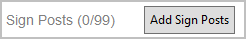
Click the Add Sign Posts button to add a new sign post.
You can add a maximum of 99 sign posts.
Click the Add Sign Posts button to add a new sign post.
You can add a maximum of 99 sign posts.

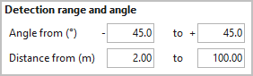
Detection range and angle
This setting lets you configure the detection range and detection angle of the sensor being used in the test. The diagram below this setting will preview the set detection range.
Detection range and angle
This setting lets you configure the detection range and detection angle of the sensor being used in the test. The diagram below this setting will preview the set detection range.

Antenna to sensor offset
This is where you specify the location of the sensor being used relative to the antenna location.

Antenna to sensor offset
This is where you specify the location of the sensor being used relative to the antenna location.
Heading smoothing settings are only applied when the VBOX unit is not using IMU integration and does not have dual antenna lock.

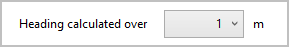
Heading calculated over
Increases the distance over which the heading is calculated to improve accuracy at low speed.
Heading calculated over
Increases the distance over which the heading is calculated to improve accuracy at low speed.

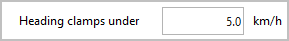
Heading clamps under
At speeds below the set threshold value, the heading will be clamped to the last heading value above the specified value.
Heading clamps under
At speeds below the set threshold value, the heading will be clamped to the last heading value above the specified value.

A Target VBOX must be configured with the latest ADAS configuration to be able to calculate road line data and accurate vehicle separation data using vehicle points.
You can transmit the ADAS configuration to any Target VBOX with an active radio link (LKTime-tg).
A Target VBOX must be configured with the latest ADAS configuration to be able to calculate road line data and accurate vehicle separation data using vehicle points.
You can transmit the ADAS configuration to any Target VBOX with an active radio link (LKTime-tg).
Note: Adding lines to a configuration will add significant time to the radio transmission.

Click this button to save the current ADAS configuration into an RCF file to be loaded into the Targets.
Click this button to save the current ADAS configuration into an RCF file to be loaded into the Targets.
Note: This setting is only available in Subject Mode.
As you configure static ADAS objects, VBOX Setup will plot them on a map.

When you have finished configuring a vehicle shape, you can see the shape of the vehicle displayed in the Diagram tab. The Subject vehicle is orange and target vehicles are green. You can see the rough shape and size as the configured vehicles are displayed next to each other.
You can find the diagram tab in the bottom right-hand corner of the ADAS menu.

The Live data tab will show you the live data for the configured vehicles.
You can find the live data tab in the bottom right-hand corner of the ADAS menu.


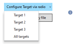
After setting the mode to Target, you must:
- Set the total number of targets in your system.
- Set which target number you have assigned to the connected VBOX unit.

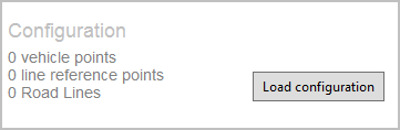
This area gives you an overview of the configuration applied to this target.
Load Configuration
You can load an RCF file that has been configured and saved in Subject mode.
This area gives you an overview of the configuration applied to this target.
Load Configuration
You can load an RCF file that has been configured and saved in Subject mode.