VBOX 4 has four isolated CAN ports that can be configured and used for a variety of applications:
- RL CAN
Used for connecting Racelogic modules and displays. - CAN
Used for input and/or output of CAN 2.0 frames. - CANFD 1
Used for logging the raw CAN FD or CAN 2.0 bus to an .ASC file. - CANFD 2
Used for logging the raw CAN FD or CAN 2.0 bus to an .ASC file.
You can use the RLCAN port to connect to Racelogic modules (TC8, FIM03, etc.), and displays (MFD Touch). You can log up to a maximum of 32 Racelogic module channels on the RL CAN port.
Connected Racelogic modules will automatically be recognised by VBOX 4 and configuration options will be presented in the Channel Setup menu in VBOX Setup.
Note: If you are connecting a module to the RL CAN port, you must make sure that the module output is set to Racelogic Mode.
You can find more information about how to configure each module in its respective user documentation.
You can use the CAN port to log data from a vehicle or sensor CAN bus or transmit CAN data to a third-party system. VBOX 4 units can log up to a maximum of 32 channels through this CAN 2.0 port.
You can configure the CAN port in the CAN menu in VBOX Setup.
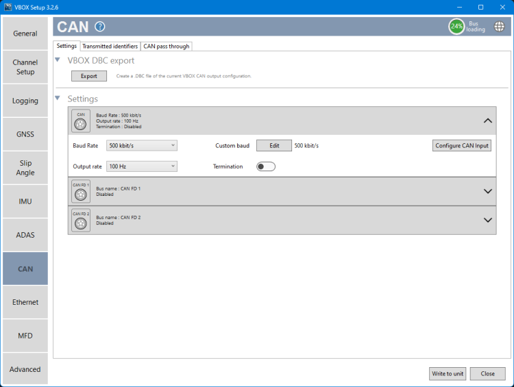
You can read more about how to configure the CAN port here.
VBOX 4 can log up to 32 channels from external CAN sources on the CAN port.
You can select the relevant CAN signals in VBOX Setup. Go to the Channel Setup menu and expand the CAN Input section. You can add signals from the Racelogic Vehicle CAN Database, by loading a .DBC file or by entering them manually.
Note: We recommend that you keep the CAN Termination off when you connect between the CAN port and a vehicle's CAN bus.
You can read more about how to select the relevant CAN signals here.
VBOX 4 can transmit VBOX data via CAN to third-party systems.
You can select the messages you wish to send via CAN on the Transmitted Identifiers tab in the CAN menu.
Note: Make sure that all transmitted identifiers are switched off when you connect the CAN port to a vehicle's CAN bus to eliminate the risk of causing errors on the vehicle's bus.
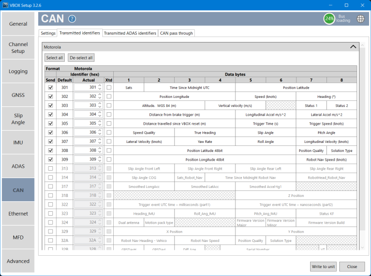
You can read more about how to select the relevant CAN messages here.
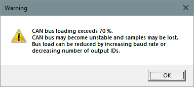
If the bus loading is more than 70%, the icon in the top right corner will become red. When it is more than 75% the icon will start flashing. If you choose to write to the unit while the CAN bus loading exceeds 70%, you will trigger a warning message.


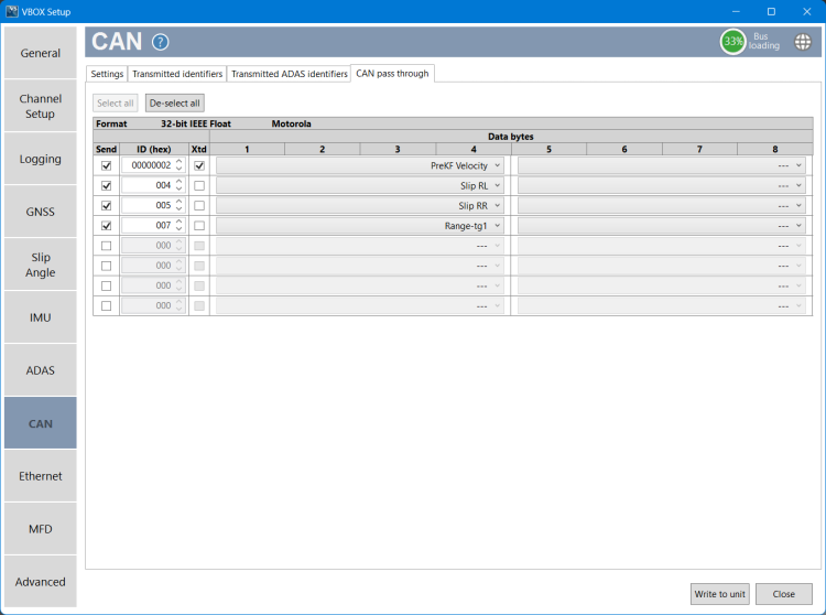
You can output additional channel data from the RL CAN port (i.e. data from a Racelogic module) on the CAN port by using the CAN Pass Through functionality. You can select messages for output using the available signal dropdown list, and configure the identifier as required.
VBOX 4 can output up to 8 user-configured CAN messages and up to 16 CAN signals on the CAN port.
Note:
- These output CAN signals will be in a 32-bit IEEE float format. 29-bit extended identifiers are optional.
- If you are loading VBOX configuration settings from a previously saved .RCF file, and there were external modules connected during the save, the selected CAN pass-through signals may not be loaded correctly. You should always check and configure the signals directly in the VBOX Setup software.
VBOX 4 units have 2 separate CANFD ports that you can use to capture data from 2 separate buses.
The CANFD 1 and CANFD 2 ports are input only and can accept either CAN 2.0 or raw CAN FD.
You can enable Full bus logging on the CANFD port and configure the CANFD settings in the CAN menu in VBOX Setup.
If you enable Full bus logging on the CANFD ports, but do not enable CANFD logging, the CANFD ports will log CAN 2.0 only.
If you enable CANFD logging, VBOX 4 will log the full vehicle bus to a time-synchronised .ASC file that will open alongside the .VBB file in VBOX Test Suite.
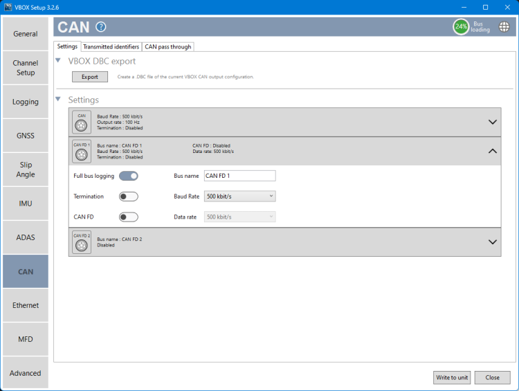
You can read more about how to configure the CAN FD ports here.