Please register your MFD Touch so that Racelogic can continue to provide you with notifications about the latest software releases and firmware upgrades for your Racelogic product and offer technical support.
Register your device here.

Image missing


Image missing
The MFD Touch display powers via the connection to the VBOX data logger. On boot-up, MFD Touch will display a splash screen. As MFD Touch will boot quicker than the VBOX, it will display 'Waiting for VBOX' with a scrolling progress bar until the VBOX is fully booted.

MFD Touch Splash Screen
The first time the unit is booted up, it will display the 6 Numerical data screen.
The supplied SD card is in a FAT32 file format, the only file format supported by MFD Touch.
If you wish to purchase a new SD card, we recommend that any card used has a write speed of more than 7 MB/s (4 MB/s absolute minimum) and a speed class of 10 (4 absolute minimum). We recommend SD cards from quality brands, such as Transcend, SanDisk, Kingston or Lexar, to ensure the best results possible.
You can find more detailed connector information on the Pinouts page.
Left Side
Right Side


SD Card
The unit uses an SD card to save and load settings, save test results and update the firmware. You can find more information here.
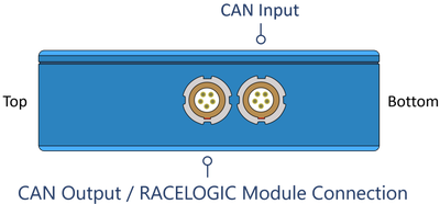
CAN Input
The bottom MFD Touch Lemo port is for connecting CAN to the VBOX using the supplied RLCAB005-C cable. CAN Output is also available on this port by using an RLVBACS024 CAN splitter. You can find more information here.
The top MFD Touch Lemo port is for CAN Output. More information on this is available here.
You can use MFD Touch as part of a daisy chain with additional Racelogic modules connected to the VBOX.
MFD Touch connects to VBOX 4 with the supplied RLCAB005-C cable from the Bottom CAN port on the MFD Touch to the RLCAN port on VBOX 4.
Image missing
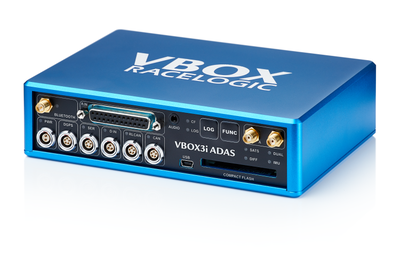
MFD Touch connects to VBOX 3i ADAS with the supplied RLCAB005-C cable, from the Bottom CAN port on the MFD Touch to the RL CAN port on the VBOX 3i ADAS.

If you are using a CAN Hub, you connect MFD Touch with the supplied RLCAB005-C cable from the Bottom CAN port on MFD Touch to the MFD port on the CAN Hub.
You can use MFD Touch as part of a daisy chain with additional Racelogic modules connected to VBOX 3i ADAS.
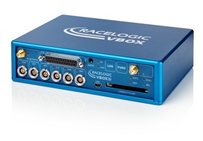
MFD Touch connects to VBOX 3i with the supplied RLCAB005-C cable, from the Bottom CAN port on the MFD Touch to the CAN port on the VBOX 3i.

If you are using a CAN Hub, you connect MFD Touch with the supplied RLCAB005-C cable from the Bottom CAN port on MFD Touch to the MFD port on the CAN Hub.
You can use MFD Touch as part of a daisy chain with additional Racelogic modules connected to VBOX 3i.
When connecting MFD Touch to a VBOX 3iS/3iSR, you must identify and connect the connector labelled CAN OUT + POWER to the bottom port on the MFD Touch. If you need help identifying the connector, you can find the relevant cable drawing here.
Image missing
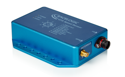
When connecting MFD Touch to a VBOX 100 Hz Speed Sensor, you must connect the cable labelled CAN OUT to the bottom port on the MFD Touch.
If you are using a wiring loom, you must identify the CAN Out connector and connect it to the bottom port on the MFD Touch. If you need help identifying the connector, you can find the relevant cable drawing here.
Image missing
MFD Touch is supplied with a Swivel Neck Richter Suction Mount (RLACS277) for mounting onto a vehicle windscreen. It can also be secured using the ¼ 20 TPI UNC screw thread on the back of the unit.

As the name suggests, you can control the MFD Touch via the capacitive touchscreen.
- The top of the screen generally contains indicative status information.
- The centre of the screen contains mode/settings information that you can navigate by tapping the forward/ back buttons or by swiping left or right on the screen.
- The bottom of the screen contains function buttons.
Image missing
If you enable IMU Integration in the connected VBOX data logger or speed sensor, MFD Touch will display the current IMU Kalman Filter status of that connected unit. The Kalman Filter Status Icon reflects the IMU LED on the connected VBOX.
Product Limitation
The KF Status will not be displayed when MFD Touch is connected to a VBOX 100 Hz Speed Sensor.
The icon has 4 possible statuses:
Solid orange indicates that IMU integration has been enabled but that the detected IMU is invalid.


Product Limitation
The Logging Status will not be displayed when MFD Touch is connected to VBOX 3iS or VBOX 100 Hz Speed Sensor.
The Record icon shows the current logging status of the connected VBOX unit.
- When the VBOX is logging data to the inserted media, the Record icon will be red.

- When the VBOX is logging data to the inserted media, the Record icon will be red.

- When the unit is not logging data to the inserted media, the Record icon will be grey.

- When the unit is not logging data to the inserted media, the Record icon will be grey.

When a media card is detected and available in the VBOX unit (the Media Status icon is green as illustrated below), you can control the logging by tapping the Record Icon on the display.
You can read more about logging with MFD Touch here.
Product Limitation
The Media Status will not be displayed when MFD Touch is connected to a VBOX 3iS or a VBOX 100 Hz Speed Sensor.
The Media Status icon displays the status of the recording media in the connected VBOX unit. The icon will change depending on the media type used:

Image missing

Image missing

Image missing

Image missing
The Satellite icon indicated the current GNSS status of the connected VBOX unit.

No satellite lock/ IMU Coast (Solution Types 0 or 6)

Standalone positional accuracy/ SBAS and Base Station DGPS corrections (Solution Types 1 or 2)

RTK Float (Solution Type 3)

RTK Fixed (Solution Type 4).

Robot Position, local co-ordinates (Solution Type 5)

This header shows the name of the current data screen. You can change this by tapping and holding or double-tapping the existing screen name. You can find more information on this here.
This area will display defined parameters dependent on which data screen you are currently on. You can find more information about the different types of data screens available and how to configure the parameters on them here.


Tap the Confirm button (when available) at the bottom right of the screen to confirm your selection.

Tap the Confirm button (when available) at the bottom right of the screen to confirm your selection.


You can enable Night Mode by tapping the Moon button at the bottom of any screen. The colour scheme will invert to suit night-time operation.
When you are in Night Mode, you can tap the Moon button again to revert to Day Mode.

You can enable Night Mode by tapping the Moon button at the bottom of any screen. The colour scheme will invert to suit night-time operation.
When you are in Night Mode, you can tap the Moon button again to revert to Day Mode.

Night Mode example
Tapping the Screenshot button will save an image of what you see displayed on the screen to the SD card inserted in MFD Touch. If the screenshot saves successfully, the LEDs will illuminate yellow in sequence from left to right (the progress of writing to the SD card). You will hear an audible confirmation notification when the screen capture is complete.
If MFD Touch was unsuccessful in saving the screenshot (if it did not have an inserted SD card or the card was full), it will display a NO SD CARD message at the top of the screen. The LEDs will flash red 2 times, and you will hear an audible error notification.
Ccaptured images will be saved as a 1.5 MB bitmap image, oriented at 90° to the original screen image, with the prefix 'screenshot'.

IMPORTANT
NEVER remove the SD card from MFD Touch while it is capturing a screenshot, as it could cause the unit to crash.
MFD Touch can display up to 6 defined VBOX parameters. There are 8 different data screens that can display a varying number of parameters and gauges. You can add a maximum of 10 screens.
When the unit is booted up for the first time, the 6 Numerical screen will be presented by default. If you want to add more screens, tap the Forward or Back buttons on the bottom right of the screen (or swipe left or right) to access the ADD/REMOVE SCREEN. It is always available before the first display screen and after the last display screen.
Image missing
Add a new screen by tapping the Add Screen button. This will open up the ADD page selection screen, where you can choose the display type you would like to add.
Image missing
Swipe left or right on the screen or use the Forward or Back arrows on the sides of the screen types to navigate through the available screens:
- 1 NUMERICAL
- 3 NUMERICAL
- 4 NUMERICAL
- 6 NUMERICAL
- ANALOGUE GAUGE
- G-BALL
- TARGET GRAPH
- BAR GRAPH
Tap the Confirm button on the bottom right of the screen to add the screen to the data screens.
If you tap the Cancel button on the bottom left of the screen, you will return to the ADD/REMOVE SCREEN without saving.
To remove a data screen, navigate to the ADD/REMOVE SCREEN and tap the Remove Screen button.
Select the required screen by swiping left or right or by using the Forward or Back arrows on the sides of the screen preview.
Tap the Confirm button on the bottom right of the screen to remove the selected screen.
Image missing
Once you have added the required screens, you can move between them by tapping the Forward or Back arrows on the bottom right of the screen or by swiping left or right. You can find more information about the different screens by clicking on the images below:
Image missing
Image missing
Image missing
Image missing
Image missing
Image missing
Image missing
Image missing
Image missing
Image missing
Image missing
Image missing
Image missing
Image missing
Image missing
Image missing
You can change the name of each data screen by either tapping and holding or double-tapping the existing screen name at the top of the display. Use the presented keyboard to enter the new screen name.
Image missing
Image missing
Image missing
Image missing
To save the new name, tap the Confirm button on the bottom right of the screen. Tap the Cancel button on the bottom left of the screen to return to the data screen without saving the new name. If you have an SD card inserted in the unit, it will remember the new name after each power cycle.
You can configure each parameter by either tapping and holding or double-tapping the existing parameter area. This will open up the screen-specific menus. For more information about the screen menus, click on the relevant display screen above.
Image missing
You can find the MFD Touch Settings menus by pressing the Settings button in the bottom left corner of the data screens.
Image missing
The General Settings contain measurement units, brightness levels, average speed calculation, reset and alert options and information about the unit.
The VBOX Settings contain file management options, such as selecting and creating file directories for the file on the connected VBOX.
The Test Settings contain test-specific configuration options.
You can use this option to load a previously saved settings file from the inserted SD card.
You can use this option to save the currently configured settings to the inserted SD card.
Return to the parameter screen by pressing the Exit button in the bottom left corner.