This page explains how to configure VBOX Touch for use.
Configuration includes preparing the unit for different applications, adjusting system behaviour, and enabling additional functionality where required.
Access configuration settings via the touchscreen interface.
The majority of the configuration is performed in the active display mode using the on-screen settings menu.
Refer to the User Interface page for more information about how to access the different settings and what and where the available options are.
Before using the unit, make sure that the basic system configuration has been completed.
This typically includes:
- Selecting preferred units (e.g. mph or km/h).
- Confirming logging behaviour.
- Ensuring system settings match your application.
These settings are sufficient for standard acceleration, deceleration, lap timing and speed tests.
Once configured, the unit is ready for use with any display mode.
Each application requires configuration in its corresponding display mode.
Use the sections below to understand the type of configuration required before starting a test.
Acceleration tests on VBOX Touch require configuration before use.
Before starting a session:
Open the Acceleration Settings to:
- Ensure the required tests are selected.
- Confirm the correct start and end speeds are defined.
Additional Options
In addition to the General Configuration described above, you can adjust the Acceleration Settings to suit your requirements by configuring:
- How results are displayed.
- If you want to be alerted when the test ends.
- If you want to use One-Foot Rollout or Slope Correct.
Deceleration tests on VBOX Touch require configuration before use.
Before starting a session:
Open the Deceleration Settings to configure the required test type.
Additional Options
In addition to the General Configuration described above, you can adjust the Decel Settings to suit your requirements by configuring:
- If you want to be alerted when the test ends.
NOTE
If you are performing a Trigger Test, refer to the Using VBOX Touch with a VBOX Brake Pedal Trigger article in the VBOX Touch Knowledge Base.
Lap Timing on VBOX Touch requires configuration before use.
Before starting a session:
Open the Lap Timing Settings to:
- Confirm the correct track layout is selected.
- Make sure that the start/finish line has been defined as required.
Lap timing will not function correctly without a valid track or start/finish reference.
Additional Options
In addition to the General Configuration described above, you can adjust the Lap Timing to suit your requirements by configuring:
- The start/finish line, required gates and track options.
- The use of rolling lap time.
- The use of standing start.
- The speed range used for Delta-V.
- The reference lap.
- If any laps should be ignored.
Speed Display requires minimal configuration.
In addition to the General Configuration described above, you can configure the speed display to suit your requirements.
Open the Speed Settings to configure:
- The number of decimal places shown in speed values.
- The level of smoothing applied to live speed data.
- How average speed is calculated.
- The target speed and associated alerts.
Additional configuration may be required depending on your setup. Some features require external inputs or system integration before they can be used.
RTK configuration is only available on VBOX Touch RTK variants.
The RTK-enabled VBOX Touch variant supports enhanced positional accuracy using correction data and are pre-configured to receive serial RTK correction messages (RTCM v3.2 MSM4).
You do not need to enable RTK settings, unless you are using an NTRIP Modem or wanting to change the baud rate/3rd tracked constellation.
Required Setup
Before using RTK functionality:
- Make sure that a compatible correction source is available (e.g. base station or network corrections).
- Confirm that the correction data is correctly received by the unit.
- Make sure that the GNSS antenna has clear sky visibility.
RTK accuracy will not be achieved unless valid correction data is available.
RTK Input
Open the Serial Port Settings.
Change the following in the RTK Input section:
When using an NTRIP Modem:
Set NTRIP Mode to Enabled and change the DGPS Baud Rate to 115200.
When using a Static Base Station:
Make sure that NTRIP Mode is set to Disabled and select the correct baud rate.
- 115200 = Racelogic Telemetry Radio (blue box).
- 38400 = Satel Radio (grey box).
The 3rd Constellation
If you want to change the 3rd tracked constellation (BeiDou or GLONASS), navigate to General Settings → GNSS Selection.
Confirm RTK Lock
Check the Satellite Status icon on the main display or go to Diagnostics screen → GPS Status to confirm that VBOX Touch has achieved satellite lock (RTK Fixed).
Refer to the User Interface page for more information about the Satellite Status indicator.
When VBOX Touch is receiving RTK corrections (RTK Fixed) is it ready for use.
CAUTION
Connect to the vehicle CAN bus at your own risk. Incorrect connection may cause damage to the vehicle or the device.
Configure CAN Input/Output
VBOX Touch can be configured to receive and transmit data via CAN.
Typical CAN configuration includes:
- Setting the CAN baud rate.
- Enabling or disabling termination.
- Selecting CAN input and output channels.
Before using CAN communication:
- Make sure that the CAN connection is correctly wired.
- Confirm the CAN baud rate matches the connected system.
- Make sure that termination is correctly configured for the CAN network.
IMPORTANT
Make sure that all CAN settings match the connected system or vehicle network. Incorrect CAN configuration will prevent communication.
RL Modules
VBOX Touch can be configured to receive data from Racelogic modules using RL Modules mode.
This allows data from connected Racelogic modules to be logged and used alongside the VBOX measurements.
Setup
- Set the CAN Mode to RL Modules.
- Make sure that the connected modules are configured for Timed CAN mode with default output message identifiers.
- Make sure that CAN termination is enabled on the relevant port.
- Configure the Module Channels:
- Select the relevant Racelogic Module(s) from the list of modules.
- Select and edit (if required) the relevant channels.
- Confirm that the modules are connected and transmitting data.
NOTE
You can find configuration files for compatibility with the VBOX Touch RL MODULES mode on the Automotive Website for quick configuration.
- Follow the link and click on the Modules tab.
- Scroll down until you see RACELOGIC Module configuration files for use with VBOX Touch.
- Click Download.
You can upload the appropriate file to the module via the VBOX Setup software.
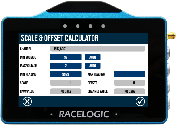
Scale & Offset
Depending on the selected module, you may get the option to calculate the scale and offset.
When reading data from a vehicle using sensor equipment, such as the Micro-Input Module, it is often necessary to convert the data into a more meaningful format, for example converting the voltage from a throttle or brake pedal into something more useful, for example a percentage pedal press.
When you select one of the following modules, you will see a CALC button next to the scale and offset values.
- Micro Input Module (MICIN) - all channels
- Mini Input Module (MIM) - analogue channels only
- Analogue to digital (ADC03) - all channels
You can read more about calculating scale and offset here.
Complete Configuration
To complete the configuration, you must confirm your channel selection on the Input Modules screen.
When you have selected one or more channels to log, tap the Exit button on the Input Modules screen.
The selected channels will be set to log and VBOX Touch will return to the CAN Settings screen.
NOTE
An incomplete configuration will be retained until one of the following things happen:
- The unit is power cycled.
- The incomplete selection is deselected.
- A selection is confirmed.
- The source database is no longer available (i.e. if the SD card with the external database is not available when accessing the select database screen).
Input
VBOX Touch can be configured to receive data from external CAN devices using Input mode.
This allows data from vehicle networks or external systems to be decoded and logged alongside VBOX measurements.
IMPORTANT
- There is a limit of 64 logged CAN channels, applied across both CAN ports.
- You must make sure that the Baud Rate and Termination settings match the expected connection on the relevant port.
Setup
- Set the CAN Mode to Input.
- Make sure that the CAN connection is correctly wired.
- Confirm that the CAN baud rate matches the connected system.
- Make sure that termination is correctly configured for the CAN network.
- Select a valid CAN database to decode incoming data.
- Select and edit (if required) the relevant channels or load a channel configuration file.
NOTE
External CAN databases must be saved on the SD card before it can be loaded onto VBOX Touch.
Complete Configuration
To complete the configuration, you must confirm your channel selection on the Select Channels to Log screen.
When you have selected one or more channels to log, tap the Exit button on the Select Channels to Log screen.
The selected channels will be set to log and VBOX Touch will return to the CAN Settings screen.
NOTE
An incomplete configuration will be retained until one of the following things happen:
- The unit is power cycled.
- The incomplete selection is deselected.
- A selection is confirmed.
- The source database is no longer available (i.e. if the SD card with the external database is not available when accessing the select database screen).
Using CAN Input Mode with Daisy Chains
When setting up a daisy chain, you must:
- Set the CAN Mode to Input.
- Make sure that the connected modules are configured for Timed CAN mode with default output message identifiers.
- Change the default output identifiers for each added unit of that type (to something unique).
- Construct or load your own (singular) database file that has channels for all the modules you are connecting to.
Output
Select Output as the CAN Mode on the relevant CAN/Serial port.
The Save Output DBC file option becomes available. Use this to export and save the CAN database (for decode purposes) to the SD card.
