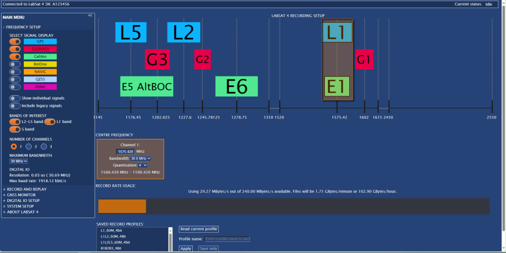
The Frequency Setup menu is designed to allow you to configure LabSat 4 remotely. In this menu, you can configure the bandwidth, quantization and number of channels you wish to record.
Model Limitations
LabSat 4 (P) variants do not have recording capabilities. While you can still adjust configurations in the Frequency Setup menu and see the Record Rate Usage, this is for visualisation purposes only, and you will not be able to record a scenario file with this LabSat 4 unit.
This is where you select the signals you want to view in the Recording Setup Chart.
Viewing the relevant signals together on the chart makes it easier to see if your setup cover the correct signals.
- GPS
- GLONASS
- Galileo
- BeiDou
- NavIC
- QZSS
- Other
You can select to view individual signals instead of just one signal block for the frequency area and you can also set it to Include legacy signals.
This is where you select the signal bands you want to include in your setup:
- L2-L5 band
- L1 band
- S band
This is where you select how many channels you want to include in your setup:
- 1
- 2
- 3
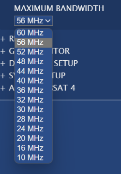
This is where you set the maximum bandwidth for the active channels in your setup.
The maximum bandwidth is the highest bandwidth that can be set for each active channel:
- 10
- 16
- 20
- 24
- 28
- 32
- 36
- 40
- 44
- 48
- 52
- 56
- 60
This is where you set the maximum bandwidth for the active channels in your setup.
The maximum bandwidth is the highest bandwidth that can be set for each active channel:
- 10
- 16
- 20
- 24
- 28
- 32
- 36
- 40
- 44
- 48
- 52
- 56
- 60

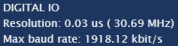
The digital recording rate depends on the selected bandwidth and quantization. This section will display the Resolution and Max baud rate required for the digital channels.

The digital recording rate depends on the selected bandwidth and quantization. This section will display the Resolution and Max baud rate required for the digital channels.
The Recording Setup chart provides a visual representation of the GNSS signals available with LabSat 4.
This chart will update as you change the configuration in the panel on the left-hand side of the window.
Drag the frequency bands across the chart to select the required frequencies.
Right-click on the chart to save it as a .png on your computer.
This will display the centre frequency highlighted by the bands on the Recording Setup chart.
In addition to dragging the frequency bands in the Recording Setup chart, you can also enter frequencies into the Centre Frequency box manually. Click in the frequency box on the relevant channel to edit it and press Enter to confirm the frequency.
This is also where you can change the Bandwidth and Quantization for each channel.
The available bandwidth options will depend on the set Maximum Bandwidth.
If your configuration is incompatible with the unit, the Web Server will highlight the relevant channel with an error to warn you about this and provide suggestions for how to fix it.
Model Limitations
The available quanitzation options will depend on the LabSat 4 model.
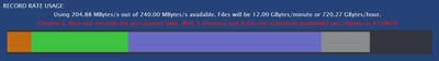
This will display the used recording rate of the available recording rate based on the configured recording setup.
The coloured blocks in the Record Rate Usage bar represent the different configured inputs:
- Orange represent Channel A
- Green represents Channel B
- Blue represents Channel C
- Grey represents all digital inputs
It also tells you how big the recorded file will be based on the recording length.
If your configuration is incompatible with the unit, the Record Rate Usage area will warn you about this.

Model Limitations
The following options will only be available when connected to a LabSat 4 (RP) variant unit.
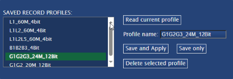
This area displays a list of the Record Profiles that have been saved.
Select a profile and click the Read current profile button to view that profile in the Recording Setup.
If you want to save your current setup as a profile, enter a name for the profile in the Profile name text box and click on the Apply button to save it and write it to LabSat 4 or the Save only button to save the profile without writing it to LabSat 4.
If you want to delete a profile, select the relevant profile from the list and click on the Delete selected profile button.
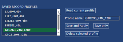
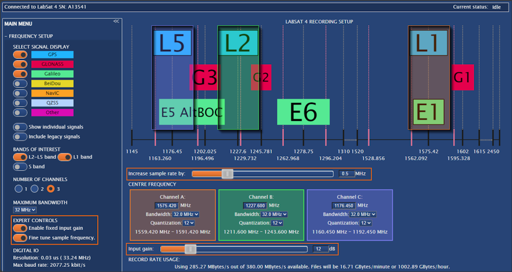
You can see the Fine Tune Sample Frequency. setting in the left-hand side of the window. When you enable it, you will see added lines in the frequency chart and a slider underneath it that you can use to aid fine-tune the sample frequency.
You can see the Enable Fixed Input Gain setting in the left-hand side of the window. When you enable it, you will see an Input Gain slider added in the Centre Frequency area that you can use to adjust the fixed input gain.
Notes:
- These settings will only be available if you enable Expert Controls on the System Setup page.
- These settings will affect the Record Rate Usage.