
The front panel display gives you the ability to record/play and monitor scenarios and to configure your LabSat 4 directly via the Settings Menu.
Move Up/Down through the menu options or the list of files.
Move Up/Down through the menu options or the list of files.

Press OK to select the highlighted option or confirm a selection.

Press OK to select the highlighted option or confirm a selection.

Press this button to start recording to a new file using the current settings.
The number in the file names will be incremented.
Press this button when LabSat 4 is recording to stop the recording.
Model Limitations
This button has no functionality on LabSat 4 (P) variants.

Press this button to start recording to a new file using the current settings.
The number in the file names will be incremented.
Press this button when LabSat 4 is recording to stop the recording.
Model Limitations
This button has no functionality on LabSat 4 (P) variants.

Press this button to start the replay of the currently highlighted file.
Press this button when LabSat 4 is replaying a file to stop the replay.

Press this button to start the replay of the currently highlighted file.
Press this button when LabSat 4 is replaying a file to stop the replay.

Press for 3 seconds to power LabSat 4 up or down.

Press for 3 seconds to power LabSat 4 up or down.

The SSD LED will flash blue when LabSat 4 records data to or replays data from the SSD.

The SSD LED will flash blue when LabSat 4 records data to or replays data from the SSD.

The SD Card LED will flash blue when LabSat 4 is running a firmware update.

The SD Card LED will flash blue when LabSat 4 is running a firmware update.

The 8 GB SD card that is included with LabSat 4 can be used for firmware upgrades and to transfer files to and from the internal SSD. You cannot use it to record/replay scenario files.
Note: To reduce the risk of any unwanted signal noise, you should remove the SD card from LabSat 4 when you are not performing a firmware update or transferring files.


The 2-pin Lemo port connects an external power supply to LabSat 4, such as mains or 12 V vehicle power.
Note: This port has an 8 to 30 V DC Power Supply input.

The 2-pin Lemo port connects an external power supply to LabSat 4, such as mains or 12 V vehicle power.
Note: This port has an 8 to 30 V DC Power Supply input.
The Charge LED will indicate if the battery pack is charging when an external power supply has been connected to LabSat 4. When the battery is charging, the LED will light blue. The battery LED will turn off when it stops charging.

You can use the USB-A port to connect USB storage devices to LabSat 4.
You can use the USB-A port to connect USB storage devices to LabSat 4.
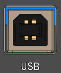
You can use the USB-B port to connect devices to LabSat 4 to receive NMEA data output from the GNSS Monitor.

You can use the USB-B port to connect devices to LabSat 4 to receive NMEA data output from the GNSS Monitor.

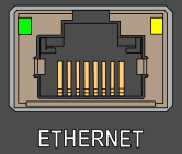
You can use the RJ45 port to connect LabSat 4 to your computer via an Ethernet connection to facilitate remote access and control of LabSat 4 in the Web Server.
You can use the RJ45 port to connect LabSat 4 to your computer via an Ethernet connection to facilitate remote access and control of LabSat 4 in the Web Server.

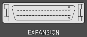
You can use the 36-way MDR port to connect 1 PPS, Digital I/O, CAN and RS232 devices to LabSat 4 to be recorded and/or replayed in the scenario files.
Model Limitations
The LabSat 4 Lite models cannot record/replay external signals.
You can use the 36-way MDR port to connect 1 PPS, Digital I/O, CAN and RS232 devices to LabSat 4 to be recorded and/or replayed in the scenario files.
Model Limitations
The LabSat 4 Lite models cannot record/replay external signals.

You can use the REF Input/Output SMA port to connect a 10 MHz reference clock (Input/Output) to LabSat 4.

You can use the REF Input/Output SMA port to connect a 10 MHz reference clock (Input/Output) to LabSat 4.

You can use the RF Output SMA port to connect the device under test to LabSat 4 to facilitate the replaying of LabSat scenario files.

You can use the RF Output SMA port to connect the device under test to LabSat 4 to facilitate the replaying of LabSat scenario files.

You can use the RF Input SMA port to connect a GNSS antenna to LabSat 4 to facilitate the recording of LabSat scenario files.
LabSat 4 comes supplied with a GNSS antenna with magnetic mounting (RLACS354). The antenna is an active device with approximately 37 dB of gain. LabSat 4 provides a 4 to 4.5 V DC bias for antenna power on the centre pin of the RF IN connector. You can also use third-party antennas, providing they are compatible with the 4 to 4.5 V bias.
If you connect LabSat 4 to an antenna that requires a higher bias voltage (e.g. 12 V), you must supply the antenna bias and insert an appropriate DC block at the RF IN connector to avoid damaging LabSat 4. You can read more about using higher bias voltage antennas here.
Model Limitations
The RF Input SMA port is for file recording and does not have functionality on LabSat 4 (P) units.
Note: To achieve the best possible result when recording and replaying with LabSat 4, we recommend that you disconnect any cables that are not relevant for the operation you are performing.

You must push the lid release catch down to unlock the lid if you need to remove or re-insert the internal SSD or the battery pack. The lid will automatically lock in place when you close it again.

You must push the lid release catch down to unlock the lid if you need to remove or re-insert the internal SSD or the battery pack. The lid will automatically lock in place when you close it again.
LabSat 4 uses a Linux .ext4 formatted drive for data storage.
Recorded data consists of the following files:
- .LS4
The RF signal data is stored in a raw binary file with the extension .LS4. - .ini
The configuration used to record and replay the data is stored in a file with the extension .ini. - .ser
Data from a RS232 log file is stored in files with the extension .ser. - .LS4D
The data from the configured digital channels will be stored in a file with the extension .LS4D. - .txt
Data from a CAN log file is stored in a readable text file.
Note: LabSat 4 can also replay .LS3W files recorded by a LabSat 3 Wideband.
IMPORTANT
When a LabSat scenario is copied from one media to another, you must make sure that all the files that are associated with that scenario are copied together.
The 8 GB SD card that is included with LabSat 4 can be used for firmware upgrades.
You can also transfer files to and from the internal SSD with SD Cards.
You cannot use it to record/replay scenario files.
Notes:
- If a file already exists on the SD card, the display will show a "File already exists" message.
- When you transfer files that are bigger than 4GB to an SD card formatted as FAT32, the display will show an "Unsuitable media" warning.
- When you transfer files to an exFAT-formatted SD card without sufficient storage, the display will show a "Not enough storage" warning.
- SD cards formatted as EXT4 are not recognised by LabSat, and so the option to copy scenarios will be unavailable.
- Scenarios recorded on and for LabSat 3 Wideband cannot be transferred to and from the internal SSD with an SD Card.
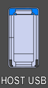
LabSat 4 units have a Host USB port that you can use to connect a USB storage device in .ext4 format.
You can record and/or replay directly to and from the USB storage device and also use it to transfer files to and from the internal SSD.
LabSat 4 includes a Samsung PM893 SSD with 7.68 TB of storage that LabSat 4 will use to record and replay scenario files to and from.
The SSD will also include demo files:
File name as displayed on LabSat 4 Display: SatGen_Static_Demo_10Min
Duration: 10minutes
Scenario Type: SatGen Simulation
RF CH1: BW 59.5MHz QUA 2bit CF 1581.840MHz
RF CH2: BW 59.5MHz QUA 2bit CF 1255.351MHz
RF CH3: BW 59.5MHz QUA 2bit CF 1189.622MHz
File name as displayed on LabSat 4 Display: UK_Dynamic_Demo
Duration: 18minutes
Scenario Type: Real World Recording
RF CH1: BW 20MHz QUA 2bit CF 1575.420MHz
RF CH2: BW 40MHz QUA 2bit CF 1176.450MHz
RF CH3: BW 20MHz QUA 2bit CF 1227.600MHz
The SSD included with your LabSat 4 is removable. To remove or insert the SSD, you must first remove the lid on the LabSat 4 unit. Push down the lid release lever on the rear panel while you push the lid towards the back of the unit. You can then remove the SSD by gently lifting it by the attached tag.
You can reattach the lid to the unit by positioning the locating lugs by the mounting holes with the LabSat logo facing forward. Press the lid down and slide it towards the front of the unit. The lid will automatically lock in place when it is closed correctly.
IMPORTANT
The LabSat 4 unit must be powered down while you remove or re-insert the SSD.
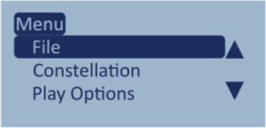
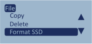
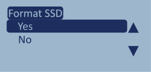
Select the following options to format the SSD via the front panel display on the LabSat 4 unit:
MENU → File → Format SDD → Yes.


IMPORTANT
When you format the SSD all the recorded data on the SSD will be erased.
You can also connect to and use Network File Systems (NFS), such as Windows File Explorer and high-speed Network Attached Storage (NAS) devices to manage scenario files. High-speed Network Attached Storage (NAS) devices can also be used for scenario storage and for scenario replays.
Note: Recording to a High-speed Network Attached Storage (NAS) device is not supported.
You can view and manage the available files on the internal SSD by connecting your LabSat 4 to a PC with an Ethernet cable. Go to the LAN settings on the LabSat 4 display to find the unit's IP address.
Menu → Setup → LAN
If required, you can enable and define a static IP address in the LAN settings. Open a file explorer window on your PC and enter \\<IP address> in the address bar.

Note: If you have enabled Network Security on LabSat 4, you must enter a username and password to access the LabSat4 folder. You can read more about Network Security and how to access the files when it is enabled here.