When accessed via a selected file, this menu will provide more information about that file and allow you to protect, copy or delete said file. This menu is also where you can format the connected SSD. This last option will always be available in the File Menu if you have a selected file or not.

Press the OK button with this selection highlighted to view the file information for the selected file.

Press the OK button with this selection highlighted to view the file information for the selected file.
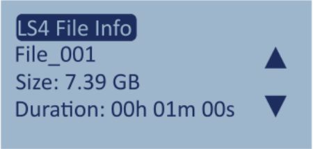
Use the arrow buttons to navigate through the following:
- The file name
- The file size
- The file duration
- The bandwidth configuration for each channel
- The quantization configuration for each channel
- The frequency configuration for each channel
- The digital channel configuration
- The CLK REF source
- Linked
- CAN Log File available
- RS232 Log File available
Press the OK button to return to the File Menu.
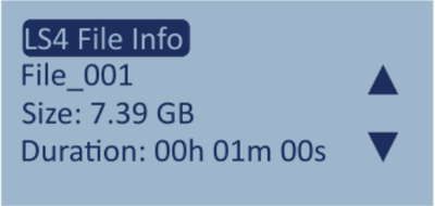

This option gives you the ability to write protect the selected file to avoid accidental copying or deletion.
Press the OK button with this option highlighted to enable Write Protect.
This will hide the Copy and Delete options for the file.

This option gives you the ability to write protect the selected file to avoid accidental copying or deletion.
Press the OK button with this option highlighted to enable Write Protect.
This will hide the Copy and Delete options for the file.

Press the OK button with this option highlighted to copy the selected file to the connected USB media.

Press the OK button with this option highlighted to copy the selected file to the connected USB media.

Press the OK button with this option highlighted to delete the selected file.

Press the OK button with this option highlighted to delete the selected file.

You can format the internal SSD directly via the File Menu. This will erase the current content on the SSD (if applicable) and format it.
Press the OK button with this option highlighted to open the Format SSD Menu.

You can format the internal SSD directly via the File Menu. This will erase the current content on the SSD (if applicable) and format it.
Press the OK button with this option highlighted to open the Format SSD Menu.

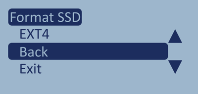
This menu will contain a list of the possible formats for the connected SSD.
Use the arrow buttons to navigate to the format you want to use and press the OK button to select it.

This menu will contain a list of the possible formats for the connected SSD.
Use the arrow buttons to navigate to the format you want to use and press the OK button to select it.

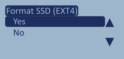
You will be asked to confirm that you want to format the SSD and clear all existing files.
Press the OK button with Yes highlighted to confirm or with No highlighted to cancel the formatting and return to the File Menu.
You will be asked to confirm that you want to format the SSD and clear all existing files.
Press the OK button with Yes highlighted to confirm or with No highlighted to cancel the formatting and return to the File Menu.

Press the OK button with this option highlighted to return to the File Menu.
Press the OK button with this option highlighted to return to the File Menu.

Press the OK button with this option highlighted to exit to the File Selection Screen.

Press the OK button with this option highlighted to exit to the File Selection Screen.

Press the OK button with this option highlighted to return to the Main Menu.

Press the OK button with this option highlighted to return to the Main Menu.

Press the OK button with this option highlighted to exit to the File Selection Screen.

Press the OK button with this option highlighted to exit to the File Selection Screen.
Model Limitations
This menu is only present on LabSat 4 (RP) variants.
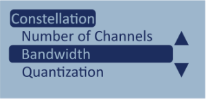
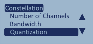
The Constellation Menu contains the settings that relate to the recording configuration of your LabSat 4 unit.

This setting gives you the ability to select the number of active channels on your LabSat 4.

This setting gives you the ability to select the number of active channels on your LabSat 4.
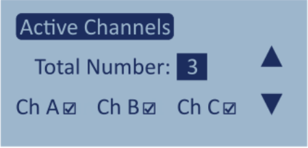
Total Number
Use the arrow buttons with this option highlighted to cycle through the number of channels you want to use.
- 1
- 2
- 3
The overview section below will automatically update when you select the number of active channels to show a tick mark for the channels that will be active.
Press the OK button to confirm your selection and return to the Constellation Menu.

This setting gives you the ability to select the maximum bandwidth available to use for each active channel.
This setting gives you the ability to select the maximum bandwidth available to use for each active channel.
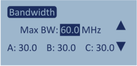
Max BW
Use the arrow buttons with this option highlighted to increase or decrease the maximum bandwidth value applied across all active channels.
You can select a maximum bandwidth level between 10 and 60 MHz.
Press the OK button to confirm the selected max bandwidth value and move to the bandwidth value for each available channel.
Use the arrow buttons to increase or decrease the bandwidth for the first channel. Press the OK button to confirm your selection and move to the next channel. When you confirm the bandwidth for the final channel you will exit the Bandwidth setting and return to the Constellation Menu.
Note: At least one of the active channels must match the level set in the Max BW setting.

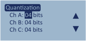
This setting gives you the ability to set the quantization applied to each individual channel.
This setting gives you the ability to set the quantization applied to each individual channel.

Use the arrow buttons to increase or decrease the quantization applied to the highlighted channel.
- 1-bit resolution
- 2-bit resolution
- 4-bit resolution
- 8-bit resolution
- 12-bit resolution
Press the OK button to confirm the selected quantization value and move to the next available channel. When you confirm the quantization for the last available channel you will exit the Quantization setting and return to the Constellation Menu.
Model Limitations
The available quantization options will depend on the LabSat 4 Model.
Constellation Not Valid
If the selected settings for Number of Channels, Bandwidth and Quantization exceed the unit's recording capability, the unit will display a message in the Constellation menu telling you to reconsider these configurations. Invalid configurations cannot be saved. You will need to change one or more settings to ensure that your unit can record the scenario as needed before you save it or discard the current changes and exit the menu.
Press the OK button with the message highlighted to view the full message.
You can see an overview of the valid configuration possibilities for LabSat 4 here.
This is, however, an overview of scenarios where the active channels have the same configuration. If you want to use a variable configuration with for the different active channels, you can check your configuration in the Frequency Setup Menu in the demo version of the Web Server.
The demo versions of the LabSat 4 Web Server and the LabSat 3 Wideband Web Server let you select the correct bandwidth, channels and quantization settings for your system so that you can see if everything falls within the relevant parameters and limitations.

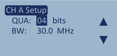
This setting gives you the ability to set the Radio Frequency for each available channel.

This setting gives you the ability to set the Radio Frequency for each available channel.
Use the arrow buttons to navigate to the channel (A, B or C) you want to change the frequency for and press the OK button.

Use the arrow buttons to navigate to the channel (A, B or C) you want to change the frequency for and press the OK button.

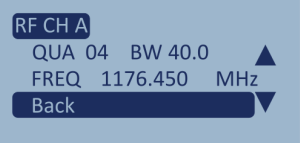
When you have selected a channel, the unit will open the Channel View, which will display the settings applied to the selected channel. Press the OK button with the quantization and bandwidth value highlighted to enter the setting selection screen and change the settings.
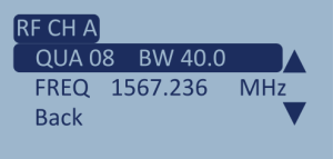
When you have selected a channel, the unit will open the Channel View, which will display the settings applied to the selected channel. Press the OK button with the quantization and bandwidth value highlighted to enter the setting selection screen and change the settings.

Use the arrow buttons to increase/decrease the quantization value. Press OK to confirm the currently set value and move to the bandwidth setting.
Use the arrow buttons to increase/decrease the bandwidth value and press OK to confirm the currently set value and return to the channel view.
Press the down arrow once to navigate to the frequency setting and press the OK button to enter the setting selection screen.

Use the arrow buttons to cycle through the available frequencies. (You will see a list of available signals for each frequency listed below.) Press the OK button to confirm your selected frequency and return to the Channel View.
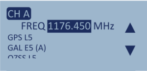
Use the arrow buttons to cycle through the available frequencies. (You will see a list of available signals for each frequency listed below.) Press the OK button to confirm your selected frequency and return to the Channel View.

Use the arrow buttons to navigate to the Back option and press OK to return to the RF Channels setting.
Use the arrow buttons to navigate to the Back option and press OK to return to the RF Channels setting.
Note:
When you configure the recording settings you will see a warning on the screen if your bands overlap. This may be an intentional choice you have made, and you can ignore the warning and save the configuration. You do, however, need to be aware that overlapping bands may cause issues with your signal.
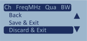
Back
Press the OK button with this option highlighted to save your selection and return to the Constellation Menu.
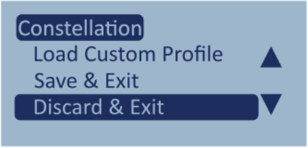
Save & Exit
Press the OK button with Save & Exit highlighted to save the changes made to the frequencies and exit to the File Selection Screen.
Discard & Exit
Press the OK button with Discard & Exit highlighted to exit the menu and return to the File Selection Screen without saving any changes.

Back
Press the OK button with this option highlighted to save your selection and return to the Constellation Menu.
Save & Exit
Press the OK button with Save & Exit highlighted to save the changes made to the frequencies and exit to the File Selection Screen.
Discard & Exit
Press the OK button with Discard & Exit highlighted to exit the menu and return to the File Selection Screen without saving any changes.

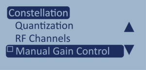
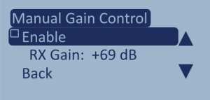
The Manual Gain Control option in the menu has a tick box next to it, indicating whether the option is enabled or disabled.
Press the OK button with the Manual Gain Control option highlighted to open the settings.
The Manual Gain Control option in the menu has a tick box next to it, indicating whether the option is enabled or disabled.
Press the OK button with the Manual Gain Control option highlighted to open the settings.

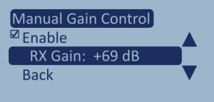
The Enable option in the settings has a tick box next to it that will indicate whether it is enabled (when ticked) or disabled.
Press the OK button with Enable highlighted to enable/disable the Manual Gain Control.
The Enable option in the settings has a tick box next to it that will indicate whether it is enabled (when ticked) or disabled.
Press the OK button with Enable highlighted to enable/disable the Manual Gain Control.

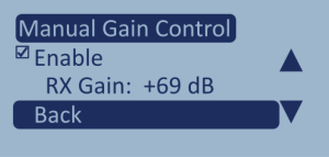
RX Gain is the gain value for Manual Gain Control.
Press the OK button with RX Gain highlighted to enter the value screen and adjust the gain value.
RX Gain is the gain value for Manual Gain Control.
Press the OK button with RX Gain highlighted to enter the value screen and adjust the gain value.

Use the arrow buttons to adjust the gain value up or down. You can set a value between 0 and +71. Press OK to confirm the set gain value and return to the Manual Gain Control settings.

Use the arrow buttons to adjust the gain value up or down. You can set a value between 0 and +71. Press OK to confirm the set gain value and return to the Manual Gain Control settings.

Press the OK button with Back highlighted to exit the Manual Gain Control settings and return to the Constellation Menu.
Press the OK button with Back highlighted to exit the Manual Gain Control settings and return to the Constellation Menu.


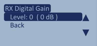
Digital Gain is designed to be used with 2- or 4-bit quantization, where the LabSat 4 unit receives low-level signals.
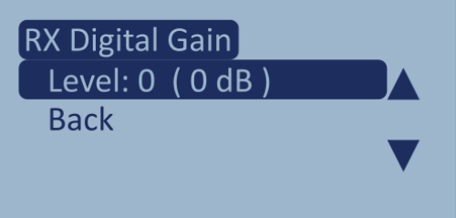
Press the OK button with the Digital Gain option highlighted to enter the RX Digital Gain menu.
Level: X (XX dB)
Press the OK button with the Level: X (XX dB) option highlighted to enter the level adjustment screen.
You can adjust the Digital Gain Shift to a value between 0 and 7. For most low-level signal applications, we recommend using a value of 1 or 2.
Use the arrow buttons to increase or decrease the level, and press the OK button to confirm the selection and return to the RX Digital Gain menu.
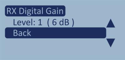
Back
Press the OK button with Back highlighted to return to the Constellation Menu.
When you have set the Digital Gain to a level between 1 and 7, the Digital Gain option in the Constellation Menu will be ticked to indicate that it is enabled and active.


Digital Gain is designed to be used with 2- or 4-bit quantization, where the LabSat 4 unit receives low-level signals.
Press the OK button with the Digital Gain option highlighted to enter the RX Digital Gain menu.
Level: X (XX dB)
Press the OK button with the Level: X (XX dB) option highlighted to enter the level adjustment screen.
You can adjust the Digital Gain Shift to a value between 0 and 7. For most low-level signal applications, we recommend using a value of 1 or 2.
Use the arrow buttons to increase or decrease the level, and press the OK button to confirm the selection and return to the RX Digital Gain menu.
Back
Press the OK button with Back highlighted to return to the Constellation Menu.
When you have set the Digital Gain to a level between 1 and 7, the Digital Gain option in the Constellation Menu will be ticked to indicate that it is enabled and active.

This option will reset the record configuration to the default configuration:
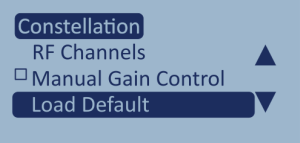
This option will reset the record configuration to the default configuration:
| Channel | Frequency | Quantization | Bandwidth |
|---|---|---|---|
| A | 1575.420 MHz | 02 | 20.0 |
| B | 1176.450 MHz | 02 | 40.0 |
| C | 1227.600 MHz | 02 | 20.0 |
Back
Press the OK button with this option highlighted to go back to the Constellation Menu without saving any changes.
Save & Exit
Press the OK button with this option highlighted to use the default configuration and go back to the File Selection Screen.
Discard & Exit
Press the OK button with Discard & Exit highlighted to exit the menu and return to the File Selection Screen without saving any changes.

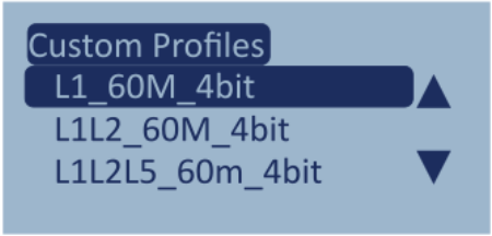
This option gives you the list of your Saved Record Profiles from the Frequency Setup page in the Web Server. You can then select one of these profiles and press the OK button to load it to your LabSat 4.
Model Limitations
If you attempt to load a custom profile with a higher quantization level than that available on your LabSat 4, the settings from the selected profile will be applied but the quantization level(s) will be adjusted to the maximum level the unit can operate with.
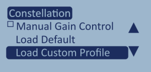
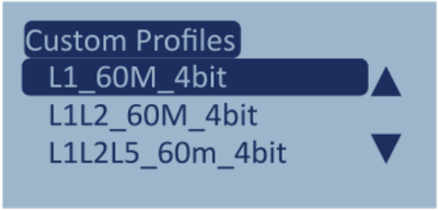
- Save and Exit
Save the changes and return to the file selection screen. - Discard and Exit
Return to the file selection screen without saving the changes.
Note: If you do not see the Save and Exit option in your menu, the configuration may be invalid.

- Save and Exit
Save the changes and return to the file selection screen. - Discard and Exit
Return to the file selection screen without saving the changes.
Note: If you do not see the Save and Exit option in your menu, the configuration may be invalid.
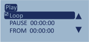
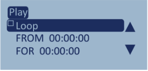
This option gives you the ability to control how LabSat 4 replays a file.

When this setting is enabled, the selected file will replay continuously.
Press the OK button with this option highlighted to enable the replay loop.
A tick mark will indicate that the setting has been enabled.
Enabling Loop will reveal the settings where you can configure the pause between the loops:
PAUSE:
Define a pause duration between loops.
Press the OK button with this option highlighted to enter the duration of the pause in hours, minutes and seconds.
FROM:
Specify a time in the scenario file where you want to start the replay.
Press the OK button with this option highlighted to enter the start time in hours, minutes and seconds.

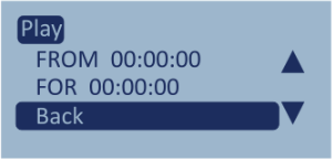
The replay variables will be available below the loop variables when Loop is enabled or below the Loop setting when it is disabled.
FROM:
Specify a time in the scenario file where you want to start the replay.
FOR:
Specify how long the scenario file will play.
The replay variables will be available below the loop variables when Loop is enabled or below the Loop setting when it is disabled.
FROM:
Specify a time in the scenario file where you want to start the replay.
FOR:
Specify how long the scenario file will play.

Press the OK button with this option highlighted to return to the Main Menu.
Press the OK button with this option highlighted to return to the Main Menu.

Press the OK button with this option highlighted to return to the File Selection Screen.
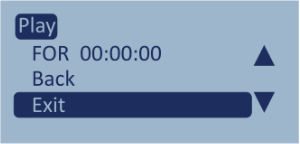
Press the OK button with this option highlighted to return to the File Selection Screen.
Model Limitations
This menu is only present on LabSat 4 (RP) variants.

This option gives you the ability to control how LabSat 4 records a file.
Specify how long the scenario file will record.
Press the OK button with this option highlighted to enter the duration of the recording in hours, minutes and seconds.

This option gives you the ability to control how LabSat 4 records a file.
Specify how long the scenario file will record.
Press the OK button with this option highlighted to enter the duration of the recording in hours, minutes and seconds.

Press the OK button with this option highlighted to return to the main menu.

Press the OK button with this option highlighted to return to the main menu.

Press the OK button with this option highlighted to exit the menu and return to the File Selection Screen.

Press the OK button with this option highlighted to exit the menu and return to the File Selection Screen.


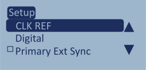
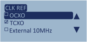
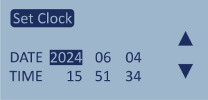
Use the arrow buttons to navigate through the clock options.
Press the OK button with an option highlighted to select it.
You can only select one of these clock references. A tick mark will identify the selected option.
- OCXO: Set the clock to OCXO (Oven-Controlled Oscillator).
- TCXO: Set the clock to TCXO (Temperature-Controlled Oscillator).
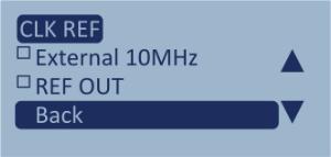
- External 10MHz: Set the clock to a 10 MHz external signal.
You can read more about using an external reference clock here.
REF OUT: Output a 10 MHz reference signal to be used by other systems (only available when you have selected OCXO or TCXO).
Use the arrow buttons to navigate through the clock options.
Press the OK button with an option highlighted to select it.
You can only select one of these clock references. A tick mark will identify the selected option.
- OCXO: Set the clock to OCXO (Oven-Controlled Oscillator).
- TCXO: Set the clock to TCXO (Temperature-Controlled Oscillator).
- External 10MHz: Set the clock to a 10 MHz external signal.
You can read more about using an external reference clock here.
REF OUT: Output a 10 MHz reference signal to be used by other systems (only available when you have selected OCXO or TCXO).

Press the OK button with this option highlighted to return to the Setup Menu.
Press the OK button with this option highlighted to return to the Setup Menu.

Press the OK button with this option highlighted to return to the File Selection Screen.

Press the OK button with this option highlighted to return to the File Selection Screen.
Model Limitations
The Digital menu is only present on LabSat 4 (RP) and LabSat 4 Core (RP) models.
The Digital menu will not be available on LabSat 4 Lite models.

This is where you can configure the 4 available digital channels on your LabSat 4. You have the same options available for each of the 4 channels.
CH1 to CH4
- CAN1: Record CAN bus channel 1
- CAN2: Record CAN bus channel 2
- 1PPS*: Record 1PPS signal from internal GNSS Monitor
- RS232: Record an RS232 signal
- DIGI 1: Record state of DIGI 1 input
- DIGI 2: Record state of DIGI 2 input
- Back: Press the OK button with this option highlighted to return to the Digital Menu.
- Exit: Press the OK button with this option highlighted to exit the Menu and return to the File Selection Screen.
*1PPS: If you want to configure 1PPS as a digital input, you must make sure that the Power Save feature has been disabled.
You can see an interactive overview of the connections for the different configurations in the LabSat 4 Web Server via your unit or by using the demo version.

Use the arrow buttons to navigate between the available channels. Press the OK button with a channel highlighted to access its channel-specific settings.

Use the arrow buttons to navigate between the available channels. Press the OK button with a channel highlighted to access its channel-specific settings.

Use the arrow buttons to go up and down the list of available digital inputs/outputs.
Press the OK button to select the highlighted option.
A tick mark will identify the selected option.

Use the arrow buttons to go up and down the list of available digital inputs/outputs.
Press the OK button to select the highlighted option.
A tick mark will identify the selected option.

Press the OK button with this option highlighted to return to the channel selection screen..

Press the OK button with this option highlighted to return to the channel selection screen..

Press the OK button with this option highlighted to return to the Setup Menu.

Press the OK button with this option highlighted to return to the Setup Menu.

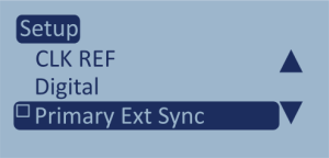
This setting enables Multi-Sync.
This will make the current LabSat 4 the primary unit when it is used in a chain with another LabSat 4.
Press the OK button with this option highlighted to enable Primary External Sync.
This setting enables Multi-Sync.
This will make the current LabSat 4 the primary unit when it is used in a chain with another LabSat 4.
Press the OK button with this option highlighted to enable Primary External Sync.
Model Limitations
- The CAN menu will not be available on LabSat 4 Lite models.
- The Log File, CAN1/CAN2 and Enable Acknowledge options will not be available on LabSat 4 (P) variants.

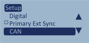
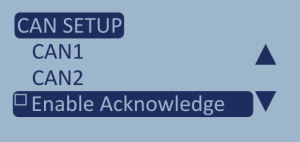
Press OK button with this option highlighted to enter the CAN Setup menu.
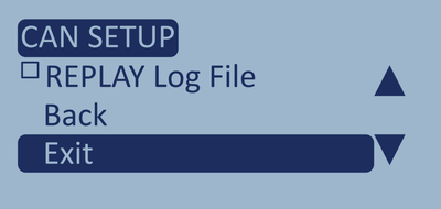
The CAN Setup Menu contains settings that enable Log File mode, replay log files and acknowledgements to the bus, and that set the baud rate for the CAN channels.
Press OK button with this option highlighted to enter the CAN Setup menu.
The CAN Setup Menu contains settings that enable Log File mode, replay log files and acknowledgements to the bus, and that set the baud rate for the CAN channels.


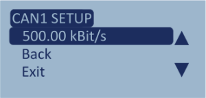
Press the OK button with one of these options highlighted to enter the CAN1 Setup / CAN2 Setup.
They contain the bit rate setting for the relevant CAN channel.
Press the OK button with the bit rate highlighted to enter the CAN Bit Rate screen.
You can enter the relevant bit rate for a CAN channel by selecting a number for each numeral space and pressing the OK button to confirm and move to the next space.
The max bit rate is 1000.00 kBit/s.
When you have confirmed the final number in the value, you will be returned to the setup screen.
Press the OK button with Back highlighted to return to the CAN menu.
Press the OK button with Exit highlighted to exit the menu and return to the File Selection Screen.

Press the OK button with this option highlighted to enable acknowledgement.
This makes LabSat 4 send an acknowledgement to the CAN bus when it has received a CAN signal.
Press the OK button with this option highlighted to enable acknowledgement.
This makes LabSat 4 send an acknowledgement to the CAN bus when it has received a CAN signal.

Press the OK button with this option highlighted to make your LabSat 4 replay a CAN log file as part of the scenario.
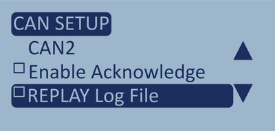
Press the OK button with this option highlighted to make your LabSat 4 replay a CAN log file as part of the scenario.

Press the OK button with this option highlighted to exit the menu and return to the Home screen.
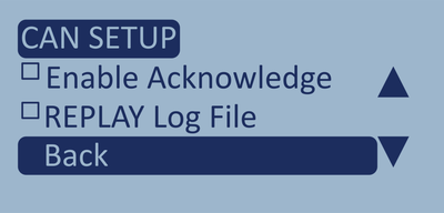
Press the OK button with this option highlighted to exit the menu and return to the Home screen.

Press the OK button with this option highlighted to exit the menu and return to the Home screen.
Press the OK button with this option highlighted to exit the menu and return to the Home screen.
Model Limitations
- The RS232 menu will not be available on LabSat 4 Lite models.
- The Log File and Port Settings options will not be available on LabSat 4 (P) variants.

Press the OK button with this option highlighted to open the RS232 Setup menu.
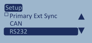
Press the OK button with this option highlighted to open the RS232 Setup menu.

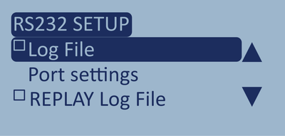

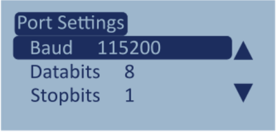
Press the OK button with this button highlighted to enter the Port Settings menu.
These settings control the baud rate, databits, stop bits and parity on the RS232 port.
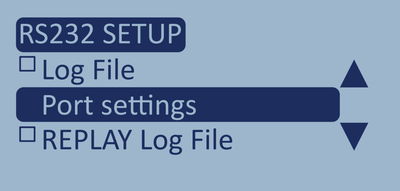
Press the OK button with this button highlighted to enter the Port Settings menu.
These settings control the baud rate, databits, stop bits and parity on the RS232 port.

Baud Rate
Press the OK button with this setting highlighted to enter the list of available baud rates.
Baud Rate
Press the OK button with this setting highlighted to enter the list of available baud rates.
- 230400
- 115200
- 57600
- 56000
- 38400
- 28800
- 19200
- 14400
- 9600
- 4800
Press the OK button with your choice highlighted to confirm your selection and return to the Port Settings.

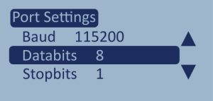
Databits
Press the OK button with this setting highlighted to enter the list of available databits.
- 8
- 7
- 6
- 5
Press the OK button with your choice highlighted to confirm your selection and return to the Port Settings.
Databits
Press the OK button with this setting highlighted to enter the list of available databits.
- 8
- 7
- 6
- 5
Press the OK button with your choice highlighted to confirm your selection and return to the Port Settings.

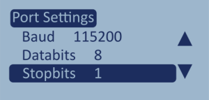
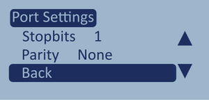
Stopbits
Press the OK button with this setting highlighted to enter the list of available stopbits.
- 1
- 2
Press the OK button with your choice highlighted to confirm your selection and return to the Port Settings.
Stopbits
Press the OK button with this setting highlighted to enter the list of available stopbits.
- 1
- 2
Press the OK button with your choice highlighted to confirm your selection and return to the Port Settings.


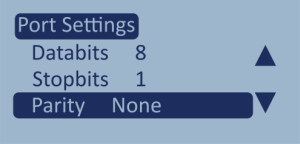
Parity
Press the OK button with this setting highlighted to enter the list of available parity options.
- None
- Odd
- Even
Press the OK button with your choice highlighted to confirm your selection and return to the Port Settings.

Parity
Press the OK button with this setting highlighted to enter the list of available parity options.
- None
- Odd
- Even
Press the OK button with your choice highlighted to confirm your selection and return to the Port Settings.

Back
Press the OK button with this option highlighted to return to the RS232 menu.
Back
Press the OK button with this option highlighted to return to the RS232 menu.

Press the OK button with this option highlighted to make your LabSat 4 replay a RS232 log file as part of the scenario.
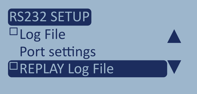
Press the OK button with this option highlighted to make your LabSat 4 replay a RS232 log file as part of the scenario.

Press the OK button with this option highlighted to return to the Setup menu.
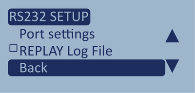
Press the OK button with this option highlighted to return to the Setup menu.

Press the OK button with this option highlighted to exit the menu and return to the File Selection screen.
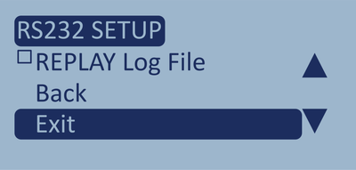
Press the OK button with this option highlighted to exit the menu and return to the File Selection screen.

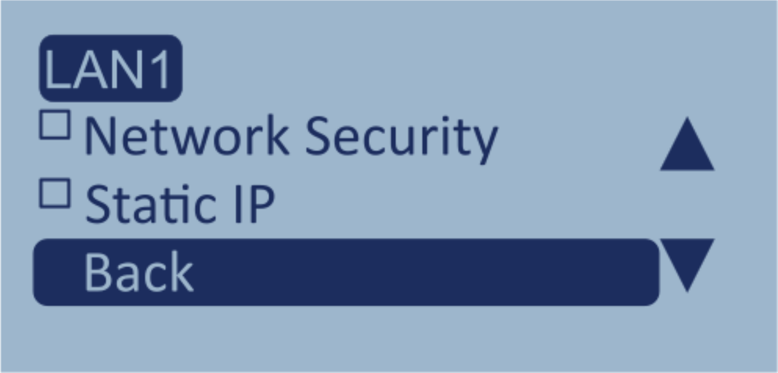
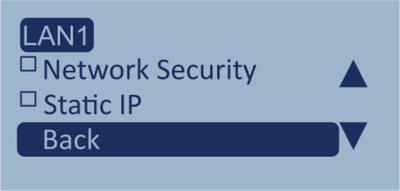
Press the OK button with this setting highlighted to enter the LAN1 menu. This menu contains settings for network security and the option to set a static IP address with specified netmask and gateway addresses.
LabSat 4 will use Dynamic Host Configuration Protocol (DHCP) by default for the IP address.
Note: The connected network must be DHCP-enabled for an IP address to be assigned.
If you require a Static IP instead, you can enable and define the IP address in the LAN1 settings menu.
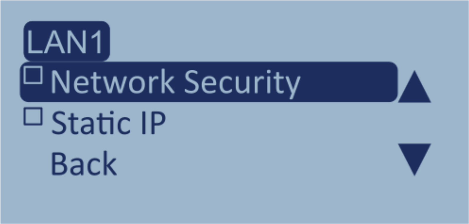
Press the OK button with this option highlighted to enable the Network Security and make the Scenarios folder in File Explorer password-protected.
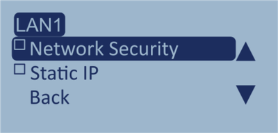
Press the OK button with this option highlighted to enable the Network Security and make the Scenarios folder in File Explorer password-protected.
When network security is enabled, you will be prompted to enter credentials to gain access to the LabSat4 folder in File Explorer.
The username is generic for all LabSat 4 units, but the password contains the connected unit's serial number.
Username: labsat4
Password: labsat4_AXXXXX
The image shows the Enter network credentials prompt when you try to access the folder in Windows File Explorer.
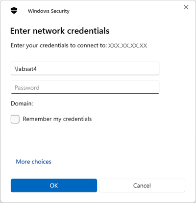
Notes:
- If you are using a Windows-based PC, you must type a backslash (\) before the username (\labsat4).
- The username and password are case-sensitive.
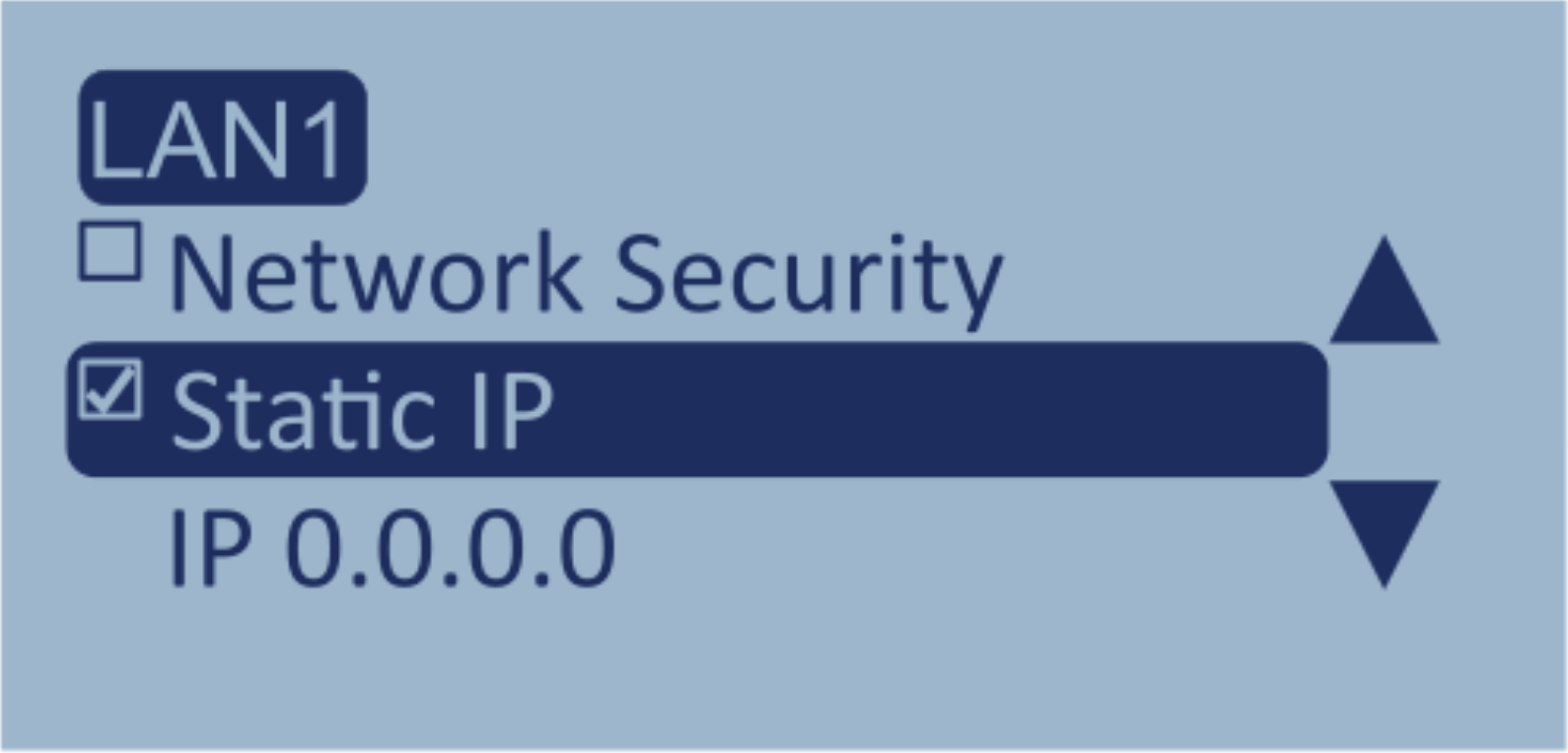

Press the OK button with this option highlighted to enable the Static IP and reveal the settings to specify the Static IP.
Press the OK button with the IP address highlighted to enter the LAN - IP screen.
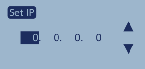
Press the OK button with the IP address highlighted again to enter the Set IP screen and edit the IP address. When you have specified the IP address you will be returned to the LAN-IP screen.
Press the OK button with Back highlighted to return to the LAN menu.
When you enable Static IP, you will also get the option to set the Netmask and Gateway addresses.
Note: When Static IP is disabled, LabSat 4 will try to obtain a DHCP IP address when you connect to the Ethernet port.
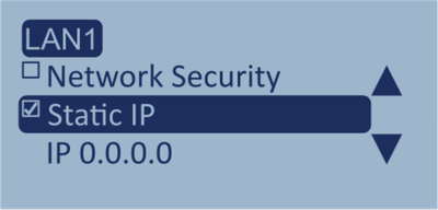


Press the OK button with this option highlighted to enable the Static IP and reveal the settings to specify the Static IP.
Press the OK button with the IP address highlighted to enter the LAN - IP screen.
Press the OK button with the IP address highlighted again to enter the Set IP screen and edit the IP address. When you have specified the IP address you will be returned to the LAN-IP screen.
Press the OK button with Back highlighted to return to the LAN menu.
When you enable Static IP, you will also get the option to set the Netmask and Gateway addresses.
Note: When Static IP is disabled, LabSat 4 will try to obtain a DHCP IP address when you connect to the Ethernet port.
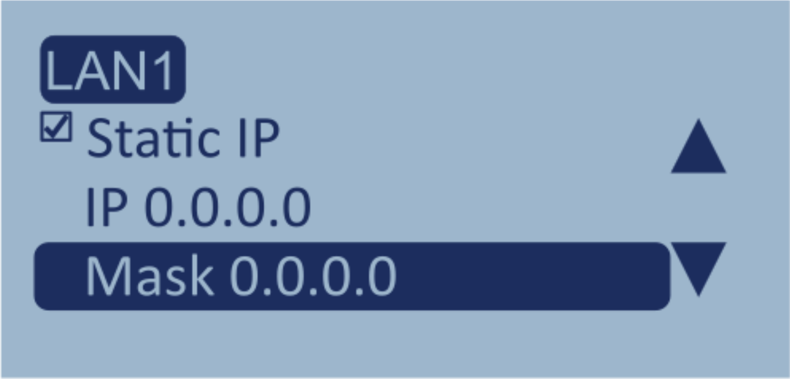

Press the OK button with the Mask address highlighted to enter the LAN -Netmask screen.
Press the OK button with the Mask address highlighted to enter the Set IP screen and edit the IP address. When you have specified the IP address, you will be returned to the LAN - Netmask screen.
Press the OK button with Back highlighted to return to the LAN menu.
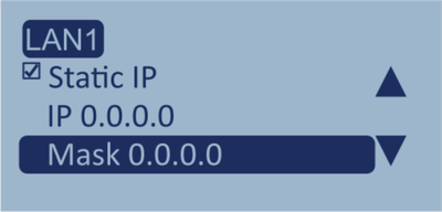
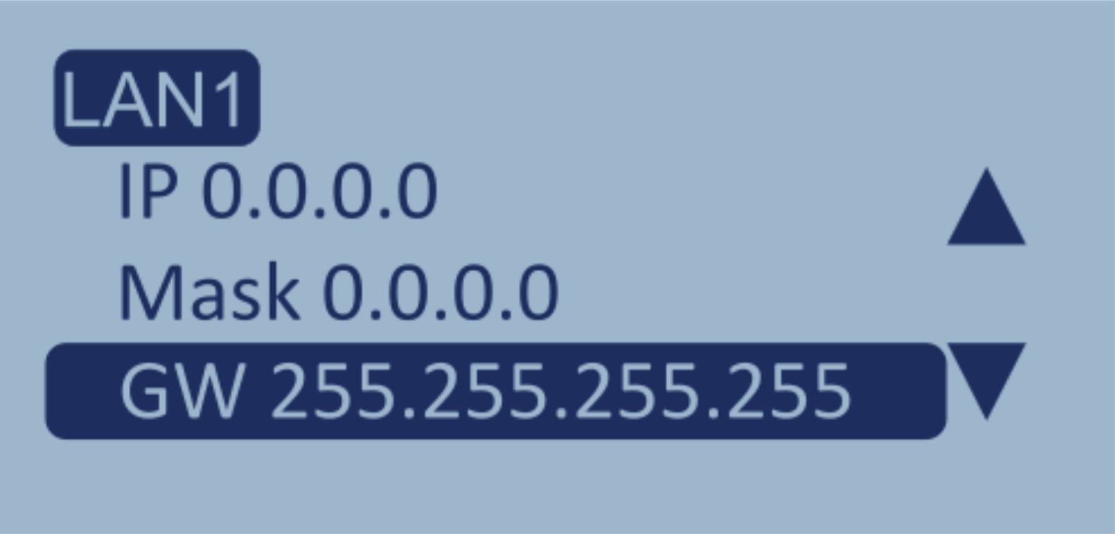
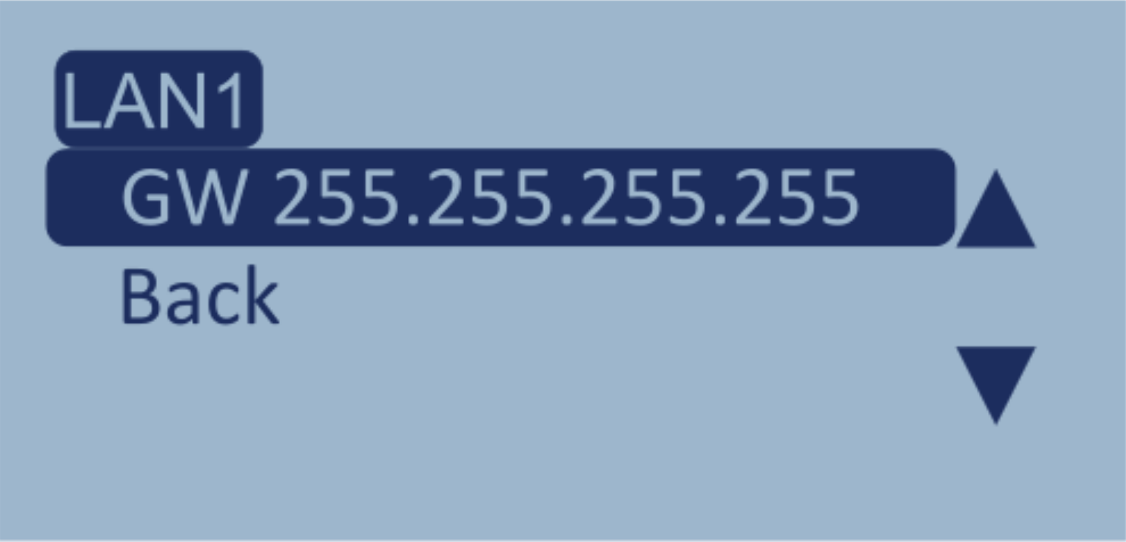
Press the OK button with the GW address highlighted to enter the LAN - Gateway screen.
Press the OK button with the GW address highlighted to enter the Set IP screen and edit the IP address. When you have specified the IP address you will be returned to the LAN-Gateway screen.
Press the OK button with Back highlighted to return to the LAN menu.
Press the OK button with this option highlighted to return to the Setup menu.
Press the OK button with this option highlighted to return to the Setup menu.

Press the OK button with this option highlighted to return to the File Selection screen.

Press the OK button with this option highlighted to return to the File Selection screen.

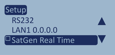
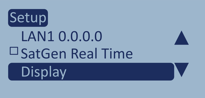
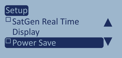
If you want to use your LabSat 4 unit for Real Time Simulations in SatGen 4, you must enable the SatGen Real Time feature (Ethernet streaming) in the Setup Menu.
Press the OK button with this option highlighted to enable/disable Ethernet streaming.
You can read more about Real Time simulations in SatGen 4 here.

Press the OK button with this option highlighted to enter the Display menu.
Press the OK button with this option highlighted to enter the Display menu.


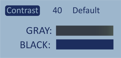
Press the OK button to enter the selection screen.
The default contrast level is 40.
Use the arrow buttons to adjust the screen contrast level between 30 and 50.
Press the OK button to confirm your selected level and return to the Display menu.

Press the OK button to enter the selection screen.
The default contrast level is 40.
Use the arrow buttons to adjust the screen contrast level between 30 and 50.
Press the OK button to confirm your selected level and return to the Display menu.

Press the OK button with this option highlighted to return to the Setup menu.

Press the OK button with this option highlighted to return to the Setup menu.

Press the OK button with this option highlighted to return to the File Selection screen.

Press the OK button with this option highlighted to return to the File Selection screen.

Press the OK button with this option highlighted to enable Power Save.
The power-save feature will make LabSat 4 dim the display after 1 minute without user interaction (button presses).
When LabSat 4 is not recording or playing scenario files, the unit will power down after 15 minutes without user interaction.

Press the OK button with this option highlighted to disable the button beeps.
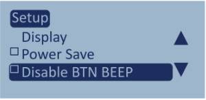
Press the OK button with this option highlighted to disable the button beeps.

Press the OK button with this option highlighted to disable all audible notifications from LabSat 4.
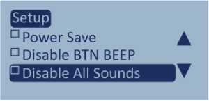
Press the OK button with this option highlighted to disable all audible notifications from LabSat 4.

Press the OK button with this option highlighted to enter the Time menu.
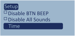
Press the OK button with this option highlighted to enter the Time menu.

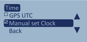
GPS UTC will sync the time to the time from the GNSS engine in your LabSat 4.
GPS UTC is enabled by default. Press the OK button with this option highlighted to disable GPS UTC.
If you disable the GPS UTC time the Manual Set Clock option will become enabled and available.

GPS UTC will sync the time to the time from the GNSS engine in your LabSat 4.
GPS UTC is enabled by default. Press the OK button with this option highlighted to disable GPS UTC.
If you disable the GPS UTC time the Manual Set Clock option will become enabled and available.

GPS UTC will sync the time to the time from the GNSS engine in your LabSat 4.
GPS UTC is enabled by default. Press the OK button with this option highlighted to disable GPS UTC.
If you disable the GPS UTC time the Manual Set Clock option will become enabled and available.

GPS UTC will sync the time to the time from the GNSS engine in your LabSat 4.
GPS UTC is enabled by default. Press the OK button with this option highlighted to disable GPS UTC.
If you disable the GPS UTC time the Manual Set Clock option will become enabled and available.

Press the OK button with this option highlighted to return to the Setup menu.

Press the OK button with this option highlighted to return to the Setup menu.

Press the OK button with this option highlighted to return to the File Selection screen.

Press the OK button with this option highlighted to return to the File Selection screen.

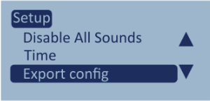
This option gives you the ability to export the set configurations to a text file on the internal SSD to share or use in future testing.
The file will be named settings.txt.
This option gives you the ability to export the set configurations to a text file on the internal SSD to share or use in future testing.
The file will be named settings.txt.

This option gives you the ability to import configurations from a settings file saved on the internal SSD.

This option gives you the ability to import configurations from a settings file saved on the internal SSD.
Model Limitations
LabSat 4 can only import configuration files that were exported from a LabSat 4 unit of the same model and variant. If you import a configuration file that is incompatible with your unit, your unit will display an error notification.

Press the OK button with this option highlighted to return to the Main menu.

Press the OK button with this option highlighted to return to the Main menu.

Press the OK button with this option highlighted to return to the File Selection screen.

Press the OK button with this option highlighted to return to the File Selection screen.
This option provides information about your LabSat 4 and the firmware on it.
Use the arrow buttons to navigate through the following data.
Serial number
- IP Address - LAN1
- IP Address - LAN2 (if enabled)
- Product Code
- Firmware Version
- FPGA
- GNSS Engine
MAC Address - LAN1
- MAC Address -LAN2 (if enabled)
- Battery Level
- TCXO Calibration Level
- OCXO Callibration Level
- PCB information
Press the OK button to return to the Main menu.
Model Limitations
This menu will only appear on LabSat 4 (RP) variants.


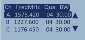
This option will display the recording settings currently configured on the unit.
Use the arrow buttons to navigate through the following data:
- The set bandwidth for Channels A, B and C
- The set quantization for Channels A, B and C
- The set frequency for Channels A, B and C
- The settings for the 4 digital channels*
- CAN log file status*
- RS232 log file status*
Press the OK button to return to the Main menu.
Model Limitations
*LabSat 4 Lite models cannot record/replay external signals.